|
» |
|
|
|
This section describes the NMMGR screens used for APPC subsystem configuration. | | | |  | NOTE: NMMGR will operate on a file of any legal name. However,
the SNA node will not activate unless the configuration file is
named NMCONFIG.PUB.SYS. | | | | |
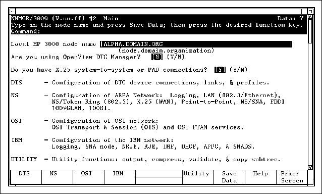
Main Screen | |
The NMMGR "Main" screen lets you select
the category of network subsystems you want to configure. The "Main" screen
is shown in Figure 4-2 “Main Screen”. To go to the "HP-IBM Configuration" screen,
press [f4] (IBM). HP-IBM Configuration Screen | |
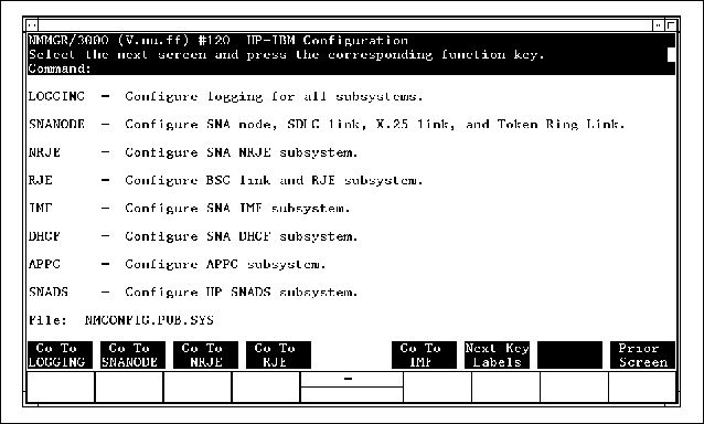
From the "HP-IBM Configuration" screen,
shown in Figure 4-3 “HP-IBM Configuration Screen”, you can select the SNA Service
or subsystem you want to configure. Figure 4-3 HP-IBM Configuration Screen To get to the APPC subsystem configuration screens, first
press [f6] (Next Key Labels), and then press [f2] (Go To APPC). APPC Configuration Screen | |
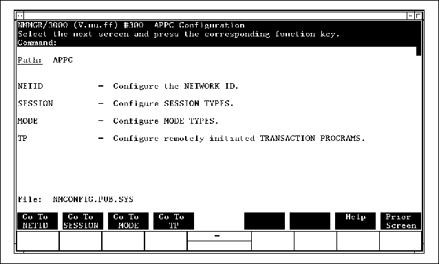
The "APPC Configuration" screen, shown in Figure 4-4 “APPC Configuration Screen”, allows you to choose among the four branches
of the APPC subsystem configuration: Network ID, Session Types,
Mode Types, and TPs. Figure 4-4 APPC Configuration Screen The network ID must be configured only if the HP 3000
will operate as a Node Type 2.1 in a peer-to-peer environment. Press [f1] (Go To NET ID) to get to the "APPC: Network ID Data" screen. To configure session types, press [f2] (Go To SESSION) to get to the "APPC: Select Session
Type" screen. To configure mode types, press [f3] (Go To MODE) to get to the "APPC: Select Mode Type" screen. To configure remotely initiated local TPs, press [f4] (Go To TP) to get to the "APPC: Select Transaction
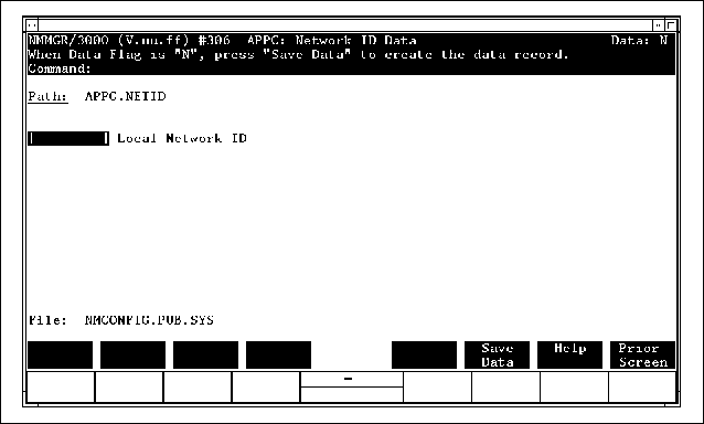
Program" screen. APPC: Network ID Data Screen | |
The "APPC: Network ID Data" screen, shown
in Figure 4-5 “APPC: Network ID Data Screen”, is where you configure the name
of the local SNA network. Configure the network ID only if your
HP 3000 will operate as a Node Type 2.1 in a peer-to-peer
environment. When you have finished entering the network ID, press [f6] (Save Data), and then press [f8] (Prior Screen) to return to the "APPC Configuration" screen. Figure 4-5 APPC: Network ID Data Screen Fields- Local Network ID
Required. Enter the network
ID of the local SNA network. For AS/400 communication, the
Local Network ID should match the RMTNETID in the Controller Description of the AS/400 configuration.
If the RMTNETID on the AS/400 is specified as *NETATTR, the Local Network ID in this screen must match the Local network ID in the AS/400 Network Attributes Table.
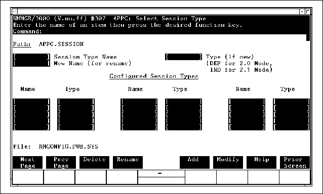
APPC: Select Session Type Screen | |
In the "APPC: Select Session Type" screen,
shown in Figure 4-6 “APPC: Select Session Type Screen”, you enter the name of a new
session type you want to configure or a previously configured session
type you want to modify. A session type is a grouping of a remote
LU, one or more local LUs, and a mode name. Every transaction program
specifies a session type name to indicate the remote LU with which
it wants to communicate and the local LU and mode it wants to use. Enter the Session Type Name and the Type (IND for independent or DEP for dependent) for the session type you wish to
configure. Then, when you press [f5] (Add) or [f6] (Modify), you will go to the next screen automatically.
If the Type is IND, you will go to the "APPC: Independent LU
Session Type Data" screen, and if the Type is DEP, you will go to the "APPC: Dependent
LU Session Type Data" screen. The "APPC: Select Session Type" screen lists
all the configured session types. Up to 60 session types may be
configured for the APPC subsystem. These session types are shared
by all LU 6.2 products running on the APPC subsystem. Press [f1] (Next Page) to see the session types listed on subsequent
pages. Figure 4-6 APPC: Select Session Type Screen Fields- Session Type Name
Required. The name of a new
session type you want to add or a previously configured session
type you want to modify. You can configure 60 session types for
the APPC subsystem. A session type name can be up to 8 alphanumeric
characters; the first character must be alphabetic. The session
type name does not have to match anything in the local or remote
configuration. - Type
This field is required if you are adding a new session type.
It is not required if you are updating the configuration for an
existing session type. Enter IND for an independent LU session type or
DEP for a dependent LU session type. An independent
LU is used for peer-to-peer communication with a Type 2.1 node,
like an AS/400, and dependent LUs are used for communication with
a host node (Type 5). For information on independent LUs, see the description
of the "APPC: Independent LU Session Type Data" screen,
later in this chapter. For information on dependent LUs, see the
description of the "APPC: Dependent LU Session Type Data" screen, later
in this chapter. If you want to change a configured session type from independent
to dependent (or from dependent to independent) you must delete
the session type and reenter it. - New Name
The new name of a session type you want to rename.
To rename a configured session type, enter its current name in the
Session Type Name field, enter its new name in the New Name field, and press [f4] (Rename).
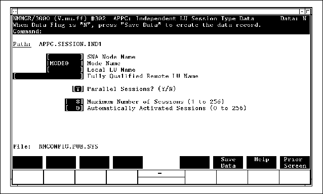
APPC: Independent LU Session Type Data Screen | |
The "APPC: Independent LU Session Type Data" screen,
shown in Figure 4-7 “Independent LU Session Type Data
Screen”, is used to configure session
types for independent LUs. Enter the data into the "APPC:
Independent LU Session Type Data" screen, press [f6] (Save Data), and then press [f8] (Prior Screen) to get back to the "APPC: Select Session
Type" screen. From there, you can configure another session
type, or you can press [f8] (Prior Screen) to get back to the "APPC Configuration" screen. An independent LU can communicate with another independent
LU on a Type 2.1 node, like an IBM AS/400. The APPC subsystem allows
the HP 3000 to act as a Type 2.1 node in a peer-to-peer
environment, where two independent LUs can establish an APPC session
between themselves without the supervision of the SSCP on a host
node. An independent LU can function as either a primary or a secondary
LU; that is, it can initiate an APPC session by sending a BIND to
the remote LU, or it can receive a BIND from the remote LU. An independent LU on the HP 3000 can carry on multiple (parallel) sessions
with a remote independent LU. To allow parallel sessions with the
remote LU, enter Y in the Parallel Sessions field of the "APPC: Independent LU Session
Type Data" screen. An independent LU can communicate with several remote LUs
at once; however, all the remote LUs with which it communicates
must be connected to the HP 3000 through the same local
SNA node (the same copy of SNA/SDLC Link/XL). (To configure
an independent LU to communicate with multiple remote LUs, configure
one session type for each remote LU, and specify the same Local LU Name for each session type. If you want independent LU sessions with remote LUs that are connected
to the HP 3000 through different local SNA nodes, you must configure
a different local independent LU for each node. Figure 4-7 Independent LU Session Type Data
Screen Fields- SNA Node Name
Required. The name of the
SNA node on which the LU for this session type resides. The SNA
node name must also be configured in the SNANODE branch of NMMGR. See the SNA Link/XL
Node Manager's Guide for information on SNA
node configuration. The SNA node name can be up to 8 alphanumeric
characters; the first character must be alphabetic. Every SNA node is a link to a remote system, so by configuring
multiple session types with different SNA node names, you can connect
the APPC subsystem to multiple remote systems. - Mode Name
Required. The name of a configured
mode type. If the HP 3000 will communicate with an AS/400,
the mode name must match the MODE in the Device Description for the partner LU on
the AS/400. A mode name can be up to 8 alphanumeric characters;
the first character must be alphabetic. The Mode Name must also be configured in the "APPC:
Select Mode Type" screen. Data for each mode type is configured
in the "APPC: Mode Type Data" screen, described
later in this chapter. The default mode name is MODE0. | | | | | NOTE: If you use the default mode name, MODE0, you still must configure a mode named MODE0 on the AS/400. | | | | |
- Local LU Name
Required. The name of the
local independent LU that will use the session type. If the HP 3000
will communicate with an AS/400, the Local LU Name must match the RMTLOCNAME in the Device Description for the partner LU on
the AS/400. The local LU must be configured on the SNA node you specified
in the SNA Node Name field. SNA nodes and LUs are configured in the SNANODE branch of NMMGR. See the SNA Link/XL
Node Manager's Guide for more information.
A local LU name can be up to 8 alphanumeric characters; the first
character must be alphabetic. Only one local independent LU is needed for each independent
LU session type, because an independent LU can conduct multiple,
simultaneous sessions with the remote LU. - Fully Qualified Remote LU Name
Required. The network ID
and LU name of the remote LU with which the local LU will communicate.
A fully qualified LU name is of the form NetworkID.LUName, where NetworkID and LUName are strings of up to 8 alphanumeric characters, each
beginning with a letter. If the HP 3000 will communicate with an AS/400,
the NetworkID part must match the Local network ID configured in the Network Attributes Table on
the AS/400, and the LUName part must match the LCLLOCNAME in the Device Description for the partner LU on
the AS/400. - Parallel Sessions
Required. Enables or disables
parallel sessions between the specified local and remote LUs. Enter
Y or N. The partner LU on the remote system must be similarly
configured for parallel or single sessions. - Y
The local LU can participate in multiple, simultaneous
sessions with the remote LU. If you specify Y, the Maximum Number of Sessions field will be set automatically to 8. You can change
the default simply by typing a different value into the field. If
the HP 3000 will communicate with an AS/400, the
SNGSSN value configured in the Device Description on
the AS/400 must be *NO. - N
The local LU may participate in only one session
at a time with the remote LU. If you specify N, the Maximum Number of Sessions field will be set automatically to 1. You can
change the default simply by typing a different value into the field.
If the HP 3000 will communicate with an AS/400, the
SNGSSN value configured in the Device Description on
the AS/400 must be *YES.
Default: Y (parallel sessions enabled) - Maximum Number of Sessions
Required. The maximum number
of APPC sessions that may be simultaneously active between the specified
local and remote LUs. If parallel sessions are disabled (Parallel Sessions = N), the Maximum Number of Sessions value must be 1. If parallel sessions are enabled (Parallel Sessions = Y), the following restrictions apply to the Maximum Number of Sessions value: The maximum
number of simultaneously active sessions for an independent session
type is 256. The maximum number of simultaneously active sessions
for the whole APPC subsystem is 256. Maximum Number of Sessions must be greater than or equal to the Automatically Activated Sessions value
If parallel sessions are enabled, the Maximum Number of Sessions value might be negotiated at session activation
time. Default: 8 - Automatically Activated Sessions
Required. The number of sessions
that will be activated automatically when the APPCCONTROL START command is issued or the APPCStart intrinsic is called. The Automatically Activated Sessions value must be less than or equal to the value
in the Maximum Number of Sessions field. The sum of the Automatically Activated Sessions values for all the session types on the APPC subsystem
must not exceed 256. Default: 0
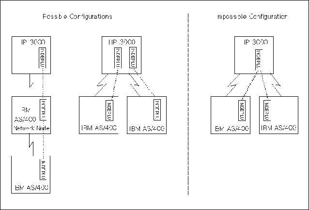
Figure 4-8 “Possible and Impossible Configurations” shows possible and impossible
configurations for independent LUs on the HP 3000. The
dotted lines in Figure 4-8 “Possible and Impossible Configurations” represent APPC sessions. Possible configurations: An independent
LU on the HP 3000 can communicate with multiple remote
independent LUs, as long as all the routes to the remote LUs pass
through the same PSI card (the same copy of SNA/SDLC Link/XL) on
the HP 3000. The remote LUs can be on the same node, or
they can be on nodes connected to a Network Node that is directly
connected to the HP 3000. Impossible configurations: An independent
LU on the HP 3000 cannot communicate with multiple remote
independent LUs if they are connected to the HP 3000 through
different SNA nodes (different PSI cards). To communicate with multiple
remote LUs that are connected to the HP 3000 through different
PSI cards, you must configure different independent LUs on the HP 3000. Figure 4-8 Possible and Impossible Configurations APPC: Dependent LU Session Type Data Screen | |
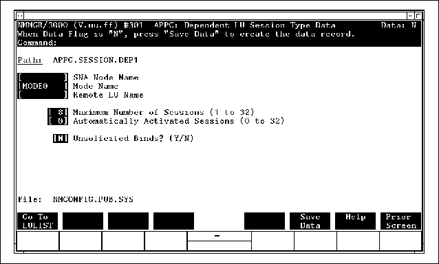
The "APPC: Dependent LU Session Type Data" screen,
shown in Figure 4-9 “Dependent LU Session Type Data Screen”, is used to configure session
types for dependent LUs. Dependent LUs can communicate only with
other dependent LUs on a host (Type 5) node. They always
function as secondary LUs; that is, they cannot initiate a session
by sending a BIND. When a dependent LU wants a session, it must
send an INIT_SELF request to solicit a BIND from the remote LU,
or it must be configured to accept unsolicited BINDs. A dependent LU can participate in only one APPC session at
a time, so you must configure at least as many dependent LUs as
you will have active dependent LU sessions. After you enter the
data into the "APPC: Dependent LU Session Type Data" screen,
press [f6] (Save Data), and then press [f1] (Go To LULIST) to get to the "APPC: Dependent LU List Data" screen. Figure 4-9 Dependent LU Session Type Data Screen Fields- SNA Node Name
Required. The name of the
SNA node on which the LUs for this session type reside. The SNA
node name must also be configured in the SNANODE branch of NMMGR. See the SNA Link/XL
Node Manager's Guide for information on SNA
node configuration. The SNA node name can be up to 8 alphanumeric
characters; the first character must be alphabetic. For troubleshooting purposes,
Hewlett-Packard recommends that the SNA Node Name match the puname operand of the PU macro on the IBM host. Every SNA node is a link to a remote system, so by configuring
multiple session types with different SNA node names, you can connect
the APPC subsystem to multiple remote systems. - Mode Name
Required. The name of a configured
mode type. The mode name must match the CICS MODENAME operand of the DFHTCT TYPE=SYSTEM macro. A mode name can be up to 8 alphanumeric
characters; the first character must be alphabetic. The
Mode Name must also be configured in the "APPC:
Select Mode Type" screen. Data for each mode type is configured
in the "APPC: Mode Type Data" screen,
described later in this chapter. The default mode name is
MODE0. If you use the default mode name, MODE0, dependent LU sessions of this type will use the
default mode name configured for the partner LU on the IBM mainframe. The
mode name configured on the IBM mainframe does not have to be MODE0. (For independent LU sessions, the mode name configured
on the remote system must match the mode name configured on the
HP 3000, even if MODE0 is used.) - Remote LU Name
Required. The name of the
remote LU with which the dependent LUs of this session type will
communicate. The Remote LU Name must match the APPLID in the Label field of the VTAM APPL definition statement. A remote LU name can be
up to 8 alphanumeric characters; the first character must be alphabetic. Only one remote LU name is configured for each session
type. The local LUs for the session type are configured in the "APPC:
Dependent LU List Data" screen. - Maximum Number of Sessions
Required. The maximum number
of APPC sessions that may be simultaneously active between the dependent
LUs of this session type and the specified remote LU. This value
is not negotiated with the remote LU. The following restrictions apply to the Maximum Number of Sessions value: The maximum
number of simultaneously active sessions for a dependent LU session
type is 32. You must have a dependent LU configured for every active
session; therefore, the Maximum Number of Sessions value may not exceed the number of dependent LUs
listed in the "APPC: Dependent LU List Data" screen. The maximum number of simultaneously active sessions
for the whole APPC subsystem is 256. Maximum Number of Sessions must be greater than or equal to the Automatically Activated Sessions value.
Default: 8 - Automatically Activated Sessions
Required. The number of sessions
that will be activated automatically when the APPCCONTROL START command is issued or the APPCStart intrinsic is called. The Automatically Activated Sessions value must be less than or equal to the value
in the Maximum Number of Sessions field. The sum of the Automatically Activated Sessions for all the session types on the APPC subsystem
must not exceed 256. Default: 0 - Unsolicited Binds
Required. Enables or disables
unsolicited BINDs from the remote LU. Enter Y or N. Hewlett-Packard recommends that you disable unsolicited
BINDs. - Y
The remote LU will initiate all APPC sessions by
sending unsolicited BINDs to the local LU. The HP 3000
will wait for a BIND rather than sending an INIT_SELF request to
solicit a BIND. The IBM host must be specifically configured to
send unsolicited BINDs. - N
The local LU will initiate all APPC sessions by
sending INIT_SELF requests to the host. The host will send a BIND
only in response to an INIT_SELF request.
Default: N (unsolicited BINDs disabled)
APPC: Dependent LU List Data Screen | |
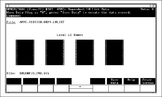
The "APPC: Dependent LU List Data" screen,
shown in Figure 4-10 “Dependent LU List Data Screen”, is where you list the dependent
LUs that are associated with a dependent LU session type. You get
to it from the "APPC: Dependent LU Session Type Data" screen
by pressing [f1] (Go To LULIST). The Path field of the "APPC: Dependent LU List
Data" screen gives the name of the dependent LU session
type to which the LUs in the list belong. You can configure a maximum of 32 LUs for a dependent LU session type.
The number of LUs you configure must be greater than or equal to the Maximum Number of Sessions value in the "APPC: Dependent LU Session
Type Data" screen. After you enter the LU names into the "APPC: Dependent
LU List Data" screen, press [f6] (Save Data), and then press [f8] (Prior Screen) twice to get back to the "APPC: Select
Session Type" screen. From there, you can configure another
session type, or you can press [f8] (Prior Screen) again to get back to the "APPC Configuration" screen. Figure 4-10 Dependent LU List Data Screen Fields- Local LU Names
The LUs you enter must be configured in the
SNANODE branch of NMMGR. The SNA node with which they
are associated in the SNANODE configuration must be the same one specified in
the SNA Node Name field of the "APPC: Dependent LU Session
Type Data" screen. See the SNA Link/XL Node
Manager's Guide for information on SNA node
and LU configuration. A local LU name can be up to 8 alphanumeric
characters; the first character must be alphabetic. For troubleshooting purposes,
Hewlett-Packard recommends that the Local LU Names match the values in the luname operand of the LU macro on the IBM host.
APPC: Select Mode Type Screen | |
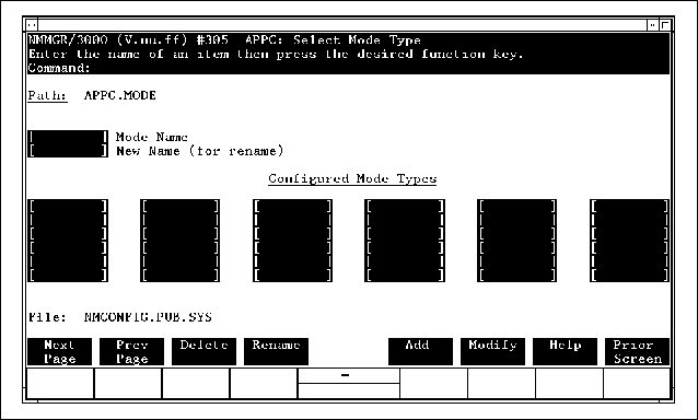
You configure mode types through the "APPC: Select
Mode Type" screen, shown in Figure 4-11 “Select Mode Type Screen”,
and the "APPC: Mode Type Data" screen, shown in Figure 4-12 “Mode Type Data Screen”. A mode type determines the following four characteristics
of a session type: The maximum size of RUs sent
by the local LU. The maximum size of RUs received by the local LU. The maximum number of RUs that the local LU can
send before it receives a response from the remote LU. The maximum number of RUs that the local LU can
receive before it must send a response to the remote LU.
Figure 4-11 Select Mode Type Screen To configure a mode type, enter the name of the mode type
you wish to add or modify in the Mode Name field, and press [f5] (Add) or [f6] (Modify). Pressing [f5] or [f6] takes you automatically to the "APPC: Mode Type
Data" screen. Fields- Mode Name
Required. The name of a new
mode you want to configure or an existing mode whose configuration
you want to modify. A mode name can be up to 8 alphanumeric characters;
the first character must be alphabetic. Up to 36 mode types may
be configured. If the HP 3000 will communicate with CICS
on an IBM host, the Mode Name must match the CICS MODENAME operand of the DFHTCT TYPE=SYSTEM macro. If the HP 3000 will communicate
with an IBM AS/400, the Mode Name must match the MODE in the Device Description for the partner LU on
the AS/400. The default mode name MODE0 is defined internally in the APPC subsystem. Its
defined RU size, for sending and receiving, is 256. The size of
its pacing window, for sending and receiving, is 7. See "APPC:
Mode Type Data Screen," later in this chapter, for more information. - New Name
The new name you want to assign to an existing mode type.
To rename a mode type, enter its old name in the Mode Name field, enter its new name in the New Name field, and press [f4] (Rename).
APPC: Mode Type Data Screen | |
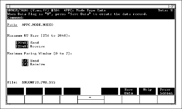
In the "APPC: Mode Type Data" screen, shown
in figure Figure 4-12 “Mode Type Data Screen”, you configure the maximum
send and receive RU sizes and the sizes of the send and receive
pacing windows. These values must be configured for every mode type
named in the "APPC: Select Mode Type" screen. Enter the data into the "APPC: Mode Type Data" screen,
and then press [f6] (Save Data). To get back to the "APPC Configuration" screen,
press [f8] (Prior Screen) twice. Figure 4-12 Mode Type Data Screen Fields- Maximum RU Size (Send)
Required. The size, in bytes,
of the largest RU that can be sent by the local LU over a session
with this mode type. For IBM mainframe communication, this must
match the receive part of the RUSIZES parameter of the MODEENT macro in the Logmode Table. For AS/400 communication,
this must match the MAXLENRU value in the Mode Description on the AS/400. Default: 2048 - Maximum RU Size (Receive)
Required. The size, in bytes,
of the largest RU that can be received by the local LU over a session
with this mode type. For IBM mainframe communication, this must
match the send part of the RUSIZES parameter of the MODEENT macro in the Logmode Table. For AS/400 communication,
this must match the MAXLENRU value in the Mode Description on the AS/400. Default: 2048 - Maximum Pacing Window (Send)
Required. The maximum number
of RUs the local LU can send before it must receive a response from
the remote LU. For IBM mainframe communication, this must match
the SRCVPAC parameter of the MODEENT macro in the Logmode Table. For AS/400 communication,
this must match the INPACING value in the Mode Description on the AS/400. Default: 7 - Maximum Pacing Window (Receive)
Required. The maximum number
of RUs the remote LU can send before it must receive a response
from the local LU. For IBM mainframe communication, this must match
the SSNDPAC parameter of the MODEENT macro in the Logmode Table. For AS/400 communication,
this must match the OUTPACING value in the Mode Description on the AS/400. Default: 7
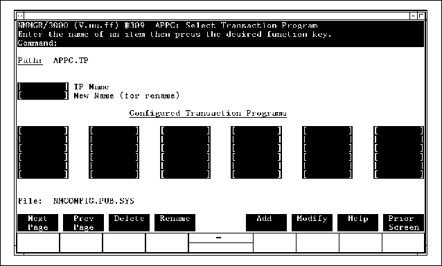
APPC: Select Transaction Program Screen | |
Any transaction programs that will call the MCGetAllocate intrinsic to accept allocate requests from remote
TPs must be configured in the "APPC: Select Transaction
Program" screen, shown in Figure 4-13 “Select Transaction Program Screen”.
The information needed to run each remotely initiated local TP is
configured in the "APPC: Transaction Program Data" screen,
which you reach by pressing [f5] (Add) or [f6] (Modify). Figure 4-13 Select Transaction Program Screen Fields- TP Name
Required. The name of a new
remotely initiated TP you want to configure or an existing remotely
initiated TP whose configuration you want to modify. A TP name can
be up to 8 alphanumeric characters; the first character must be
alphabetic. Up to 256 TP names may be configured. The remote TP sends a TP name to indicate the local TP
with which it wants a conversation. When the APPC subsystem receives
the local TP name from the remote TP, it streams a job that runs
the local TP. The job name for each remotely initiated local TP
is configured in the "APPC: Transaction Program Data" screen. The TP Name field must match the TP name sent by the remote
TP. It must also match the LocalTPName parameter of the local TP's TPStarted intrinsic call, and it must match the LocalTPName parameter of the local TP's MCGetAllocate intrinsic call.
| | | | | NOTE: On older versions of the APPC subsystem, the remote
TP sends the job name in its allocate request. To avoid changing
remote Taps that work with older versions of the APPC subsystem,
make the TP Name field of the "APPC: Select Transaction
Program" screen (and the LocalTPName parameter in the local TP) match the name of the job
file and the job name in the JOB card statement of the file. | | | | |
- New Name
The new name you want to assign to a configured
TP. To rename a TP, enter its old name in the TP Name field, enter its new name in the New Name field, and press [f4] (Rename).
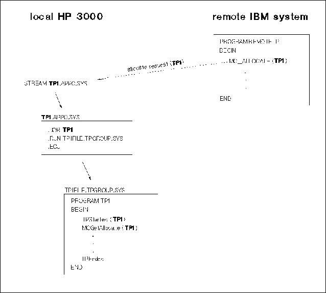
Figure 4-14 “Startup of Remotely Initiated TP” shows how remotely initiated TPs
are started. All of the following values must match: The TP Name configured in the "APPC: Select Transaction
Program" screen. The local TP name sent by the remote TP in the allocate
request. The LocalTPName parameter of the TPStarted intrinsic. The LocalTPName parameter of the MCGetAllocate intrinsic.
Figure 4-14 Startup of Remotely Initiated TP APPC: Transaction Program Data Screen | |
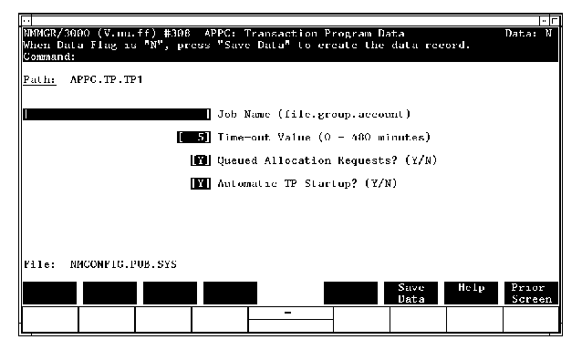
The "APPC: Transaction Program Data" screen,
shown in Figure 4-15 “Transaction Program Data Screen”, indicates the following things: The location of the job file used to
run the TP. How long the local TP's MCGetAllocate intrinsic call will wait for an allocate request
from the remote TP before timing out. Whether allocate requests from the remote TP should
be queued to wait for the current local TP process to call the
MCGetAllocate intrinsic, or whether a new local TP process should
be started for every allocate request. How the TP will be started—manually by
a user or automatically by the APPC subsystem.
Figure 4-15 Transaction Program Data Screen Fields- Job Name
Required. This is the 26-character
location (filename.groupname.accountname) of the job file that runs the local TP. This file
must not contain any lockwords. When the APPC subsystem receives
an allocate request from the remote TP, it streams this job, which
runs the local TP. If you want to start the local TP manually, leave this field
blank and configure N in the Automatic TP Startup field. - Time-out Value
This parameter tells the APPC subsystem how long
to wait for an allocate request from the remote TP after the local
TP calls the MCGetAllocate intrinsic. If the timer expires before an allocate
request arrives, the MCGetAllocate intrinsic returns with a status info value of
+29. For more information on the MCGetAllocate intrinsic, see the LU 6.2 API Application
Programmer's Reference Manual. Allowable Time-out Values are as follows: - 1-480
minutes
If Queued Allocate Requests = Y. (A Time-out Value of 0 is not allowed if allocate requests are queued.)
- 0-480 minutes
If Queued Allocate Requests = N
- Default:
5 minutes, if Queued Allocate Requests = Y 0 minutes, if Queued Allocate Requests = N
- Queued Allocate Requests?
Required. This parameter
tells the APPC subsystem whether to queue allocate requests from
the remote TP until the current local TP process calls the
MCGetAllocate intrinsic, or whether to initiate a new TP process
for every allocate request that arrives from the remote TP. - Y
The local TP accepts queued allocate requests, so
only one instance of it may be running at once. It must be written to
conduct multiple conversations initiated by the remote TP. (It must make
multiple calls to the MCGetAllocate intrinsic.) If the local TP is not running when
an allocate request arrives from the remote TP, the APPC subsystem
runs the local TP. If the local TP is running and in conversation
when an allocate request arrives, the allocate request is queued until
the local TP deallocates the current conversation and calls
MCGetAllocate again. (See Figure 4-17 “Example Configuration, One Session
Type”.)
- N
The local TP does not accept queued allocate requests,
so multiple instances of it may be running at once. It must be written
to conduct only one remotely initiated conversation. (It must make only
one call to the MCGetAllocate intrinsic.) Every time an allocate request arrives
from the remote TP, the APPC subsystem creates a new instance of
the local TP.
Default: Y - Automatic TP Startup?
This parameter tells the APPC subsystem whether
or not to stream a job to run the local TP when an allocate request
arrives from the remote TP. - Y
The APPC subsystem will start the local TP automatically
by streaming a job when it receives an allocate request from the
remote TP. If the local TP is configured to accept queued allocate requests,
the APPC subsystem will stream the job only once. If the local TP is
not configured to accept queued allocate requests, the APPC subsystem will
stream the job to start a new TP process every time it receives
an allocate request from the remote TP.
- N
The APPC subsystem will not start the local TP automatically.
The user must start the local TP by issuing the MPE RUN command or by streaming a job that issues the RUN command.
| | | | | NOTE: While you are developing and debugging a remotely initiated
TP, you might want to start it manually. However, after the TP has
been debugged, Hewlett-Packard recommends that you allow the APPC subsystem
to start it up. | | | | |
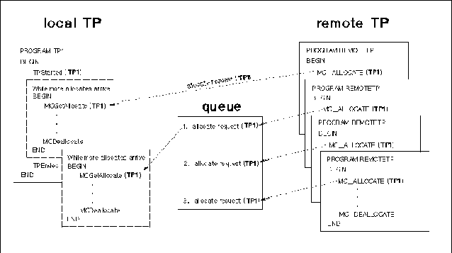
Figure 4-16 “Receiving Queued Allocate Requests” shows how allocate requests from
the remote TP can be queued to wait until the local TP calls the
MCGetAllocate intrinsic. The TP in Figure 4-16 “Receiving Queued Allocate Requests” loops
through the same conversation, beginning with MCGetAllocate and ending with MCDeallocate, until it receives the last allocate request. The TP could be written to handle a predetermined number of
allocate requests, or it could loop through the conversation until
the last MCGetAllocate call timed out because the queue was empty. When MCGetAllocate times out, it returns with a status value of +29.
The MCGetAllocate time-out value is configured in the "APPC:
Transaction Program Data" screen. Figure 4-16 Receiving Queued Allocate Requests |