|
|
|
|
APPC Subsystem on MPE XL Node Manager's Guide: HP 3000 MPE/iX Computer Systems > Appendix B Sample ConfigurationHP 3000 Configuration |
|
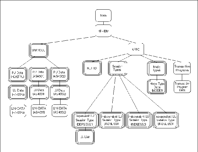
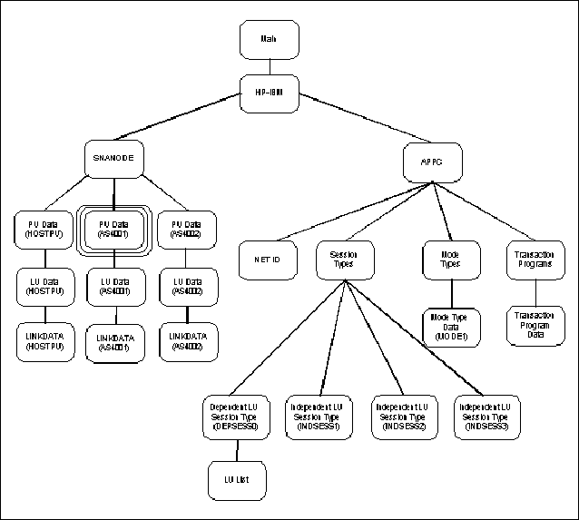
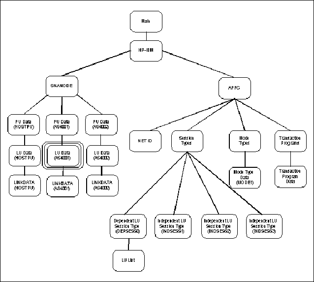
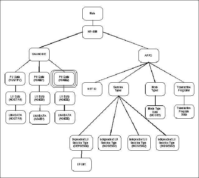
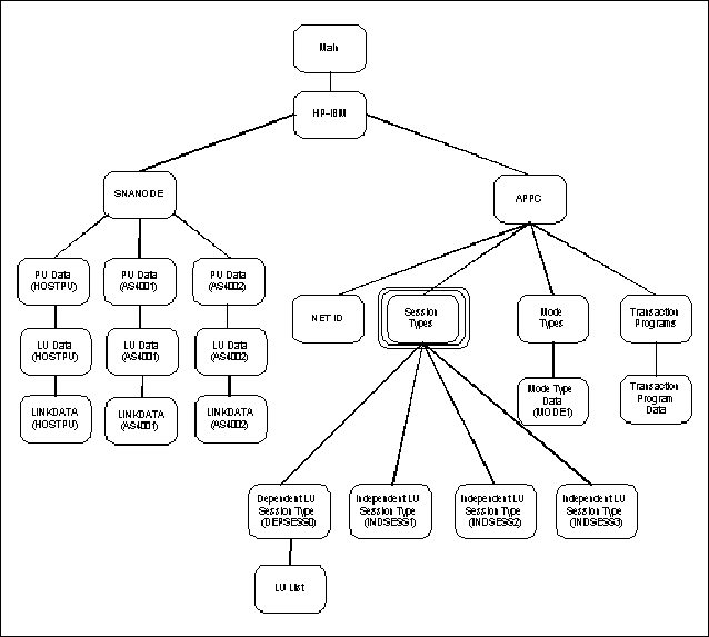
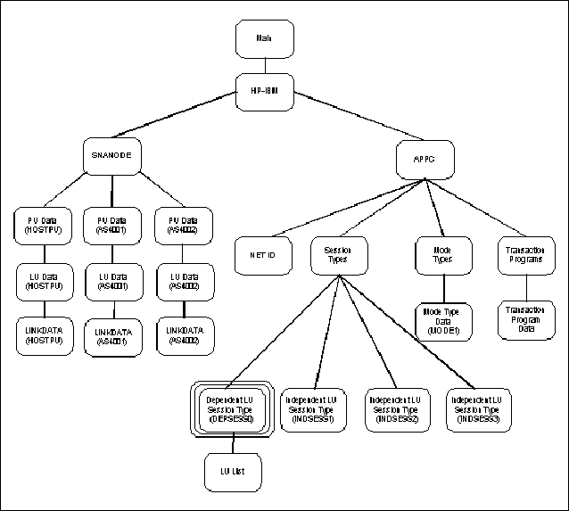
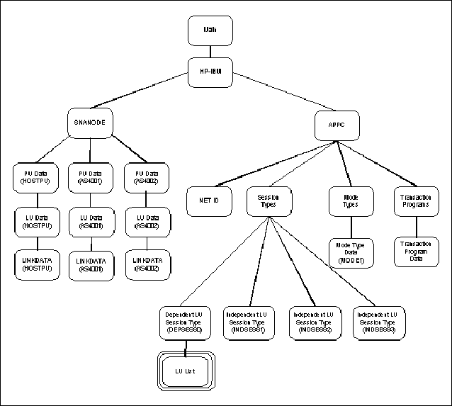
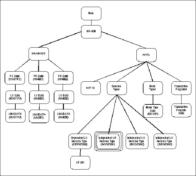
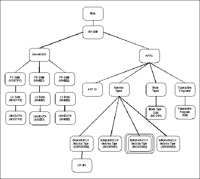
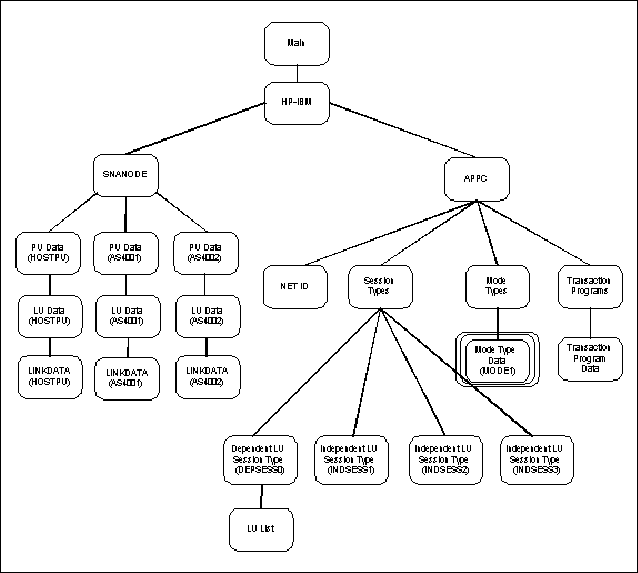
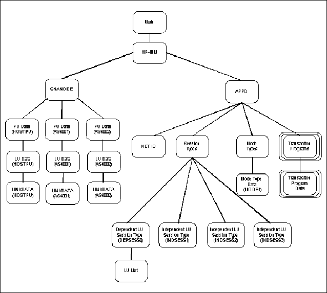
Figure B-2 “NMMGR Screen Structure” shows the NMMGR screen structure for the LU 6.2 configuration shown in Figure B-1 “Example Configuration”. The configuration must be performed across two separate NMMGR subtrees: "SNANODE" and "APPC". You select the subtree you want to configure from the list on the "HP-IBM Configuration" screen. The screens discussed in this appendix have been highlighted in Figure B-2 “NMMGR Screen Structure”. The following NMMGR screens are used to illustrate this configuration example:
The discussion of each screen includes an illustration of the screen, a diagram showing where it fits into the NMMGR screen structure, and a description of the items configured in it.
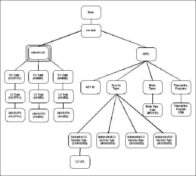
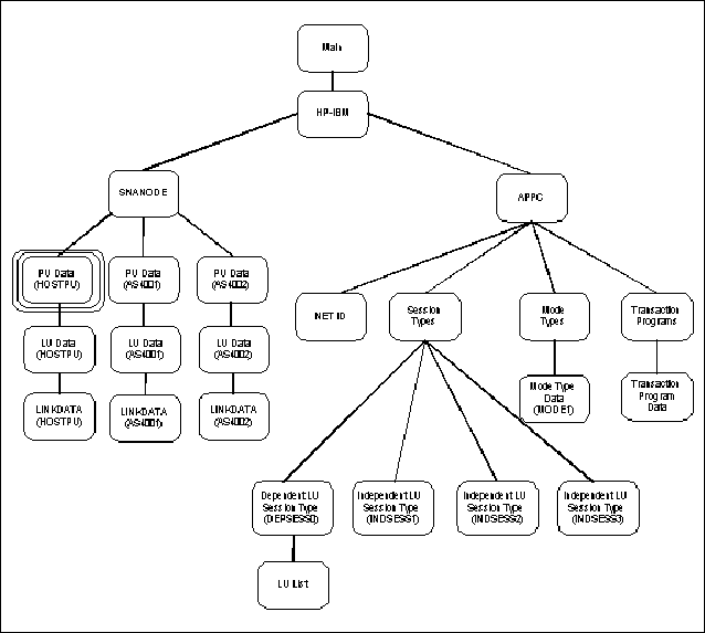
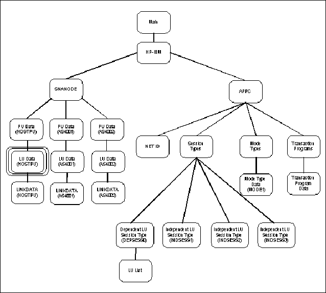
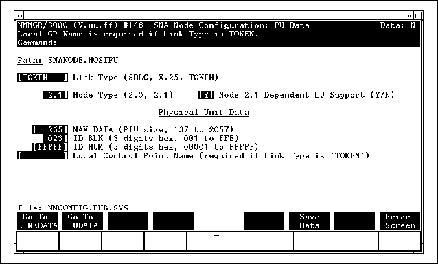
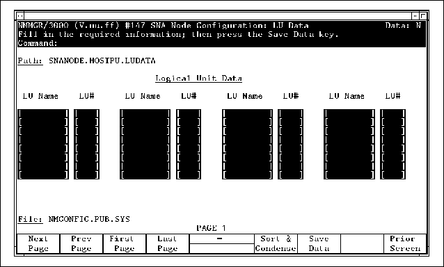
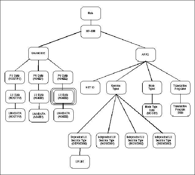
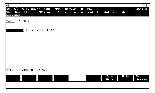
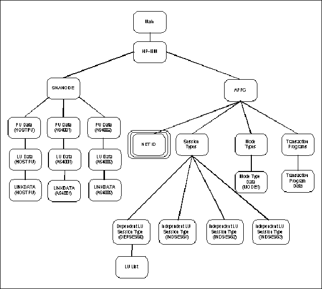
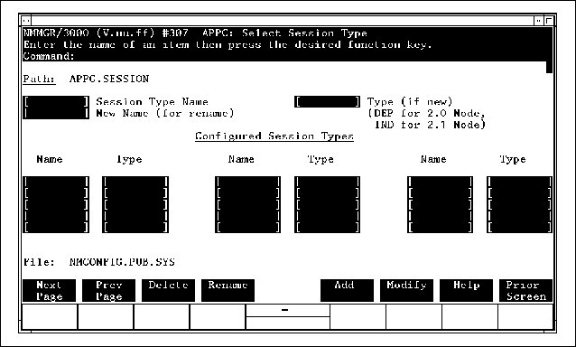
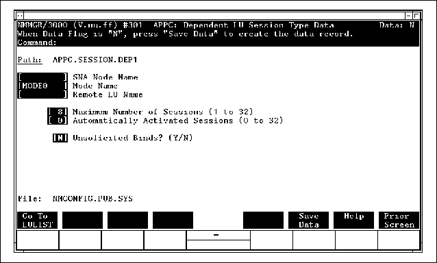
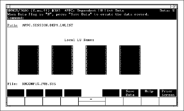
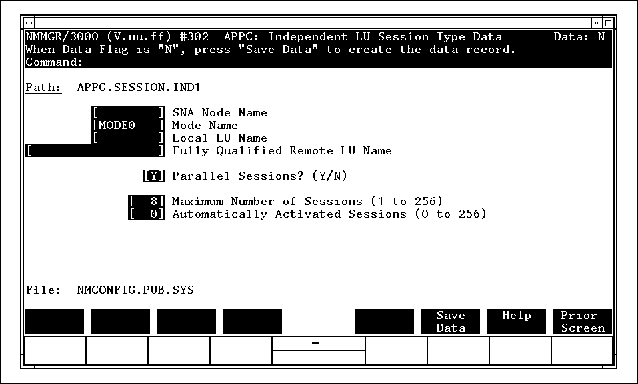
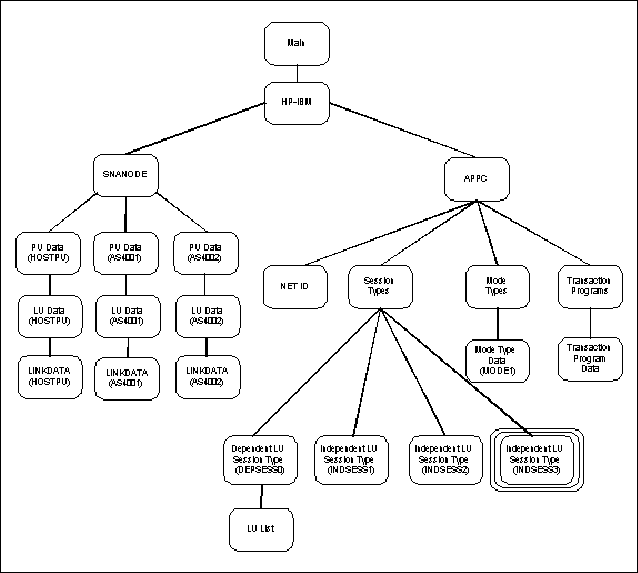
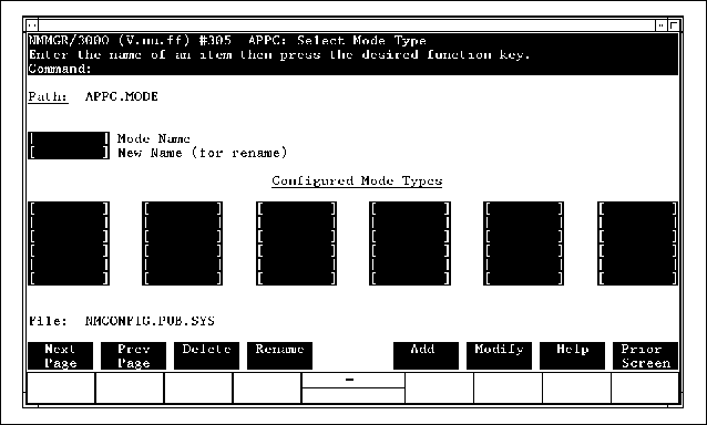
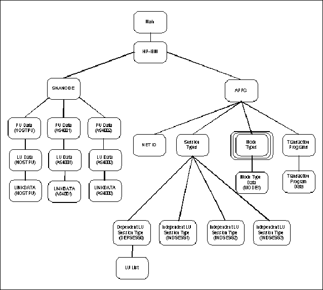
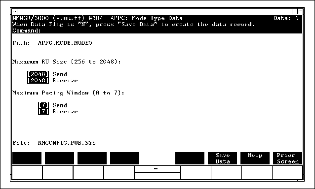
Figure B-3 “Example SNA Node Configuration Screen” shows the "SNA Node Configuration" screen. Three nodes are configured in it: HOSTPU, AS4001 and AS4002. Each node requires a separate copy of SNA/SDLC Link/XL, which links the HP 3000 to a remote system. The SNA node name HOSTPU matches the PU name configured on the IBM host. The SNA node names AS4001 and AS4002 match the RMTCPNAME (remote control point name) values configured on the two AS/400s. The following diagram as shown in Figure B-4 “SNANODE Screen Structure” shows how the "SNA Node Configuration" screen fits into the NMMGR screen structure. The SNA nodes configured here will be entered in the "APPC: Dependent LU Session Type Data" and "APPC: Independent LU Session Type Data" screens for the session types that will use these nodes. Figure B-5 “Example SNANODE PU Data Screen (HOSTPU)” shows the "SNA Node Configuration: PU Data" screen for node HOSTPU. The Node Type for HOSTPU is configured as 2.0, because all the LUs using this node are dependent LUs. Independent LUs must be configured on Type 2.1 nodes. If you wanted to configure both independent and dependent LUs on the same node, you would configure it as a Node Type 2.1, and you would specify Y in the Node 2.1 Dependent LU Support field. The following diagram as shown in Figure B-6 “PU Data (HOSTPU) Screen Structure” shows how the "SNA Node Configuration: PU Data" screen for HOSTPU fits into the NMMGR screen structure. Figure B-7 “Example SNANODE LU Data Screen (HOSTPU)” shows the "SNA Node Configuration: LU Data" screen for node HOSTPU. The four LUs configured here are used by the session type DEPSESS1, the only session type configured to use this node. The LU names configured here match the LU names configured on the IBM host. The following diagram shown in Figure B-8 “LU Data (HOSTPU) Screen Structure” shows how the "SNA Node Configuration: LU Data" screen for HOSTPU fits into the NMMGR screen structure. The LUs configured here will be entered in the "APPC: Dependent LU List Data" screen for session type DEPSESS1. Figure B-9 “Example SNANODE PU Data Screen (AS4001)” shows the "SNA Node Configuration: PU Data" screen for node AS4001. The Node Type for AS4001 is configured as 2.1, because the HP 3000 functions as a peer node when it communicates with an AS/400. Since no dependent LUs will use AS4001, the Node 2.1 Dependent LU Support field is set to N. The ID BLK and ID NUM fields, together, make up the EXCHID configured in the Controller Description on the AS/400. (The EXCHID in the Controller Description, for this example configuration, is 05600001.) The following diagram shown in Figure B-10 “PU Data (AS4001) Screen Structure” shows how the "SNA Node Configuration: PU Data" screen for AS4001 fits into the NMMGR screen structure. Figure B-11 “Example SNANODE LU Data Screen (AS4001)” shows the "SNA Node Configuration: LU Data" screen for node AS4001. The independent LU configured here is used by two session types: INDSESS1 and INDSESS2. The LU# field must be left blank for an independent LU. The LU name HPINDLU1 must match the RMTLOCNAME (remote location name) configured in the Device Description on the AS/400. The following diagram shown in Figure B-12 “LU Data (AS4001) Screen Structure” shows how the "SNA Node Configuration: LU Data" screen for AS4001 fits into the NMMGR screen structure. The LU configured here will be entered in the "APPC: Independent LU Session Type Data" screens for session types INDSESS1 and INDSESS2. Figure B-13 “Example SNANODE PU Data Screen (AS4002)” shows the "SNA Node Configuration: PU Data" screen for node AS4002. The ID BLK and ID NUM fields, together, make up the EXCHID configured in the Controller Description on the AS/400. (The EXCHID in the Controller Description, for this example configuration, is 05600002.) The following diagram shown in Figure B-14 “PU Data (AS4002) Screen Structure” shows how the "SNA Node Configuration: PU Data" screen for AS4002 fits into the NMMGR screen structure. Figure B-15 “Example SNANODE LU Data Screen (AS4002)” shows the "SNA Node Configuration: LU Data" screen for node AS4002. The independent LU configured here is used by session type INDSESS3. The LU# field must be left blank for an independent LU. The LU name HPINDLU2 must match the RMTLOCNAME (remote location name) configured in the Device Description on the AS/400. The following diagram shown in Figure B-16 “LU Data (AS4002) Screen Structure” shows how the "SNA Node Configuration: LU Data" screen for AS4002 fits into the NMMGR screen structure. The LU configured here will be entered in the "APPC: Independent LU Session Type Data" screen for session type INDSESS3. Every node configured in the "SNA Node Configuration" screen must have its communications link parameters and phone data configured in the "SNA Node Configuration: SDLC Link Data" screen. The "SNA Node Configuration: SDLC Link Data" screen is not shown here, but it is fully documented in the SNA Link/XL Node Manager's Guide. The following diagram shown in Figure B-17 “LINKDATA Screen Structures” shows how the "SNA Node Configuration: SDLC Link Data" screens for HOSTPU, AS4001 and AS4002 fit into the NMMGR screen structure. If your HP 3000 will operate as a Type 2.1 node, you must configure the identifier for your local network in the "APPC: Network ID Data" screen. Figure B-18 “Example Network ID Data Screen” shows the "APPC: Network ID Data" screen for the example configuration illustrated in this appendix. The Local Network ID matches the RMTNETID configured in the Device Description on the AS/400. The following diagram shown in Figure B-19 “NET ID Screen Structure” shows how the "APPC: Network ID Data" screen fits into the NMMGR screen structure. Figure B-20 “Example Select Session Type Screen” shows the "APPC: Select Session Type" screen. Four session types are configured for the APPC subsystem: DEPSESS1, INDSESS1, INDSESS2, and INDSESS3. DEPSESS1 communicates with an IBM mainframe through node HOSTPU. INDSESS1 and INDSESS2 communicate with IBM AS/400 #1 through node AS4001. INDSESS3 communicates with IBM AS/400 #3 through node AS4002. AS/400 #3 is not directly connected to the HP 3000; sessions of type INDSESS3are routed to AS/400 #3 through AS/400 #2, which is directly connected to the HP 3000. The following diagram shown in Figure B-21 “Session Types Screen Structure” shows how the "APPC: Select Session Type" screen fits into the NMMGR screen structure. Figure B-22 “Example Dependent LU Session Type Screen” shows the "APPC: Dependent LU Session Type Data" screen for session type DEPSESS1. Two APPC sessions are configured to activate automatically at subsystem startup. Beyond the automatically activated sessions, two more sessions can be activated before the maximum session limit for DEPSESS1 is reached. See Chapter 5 “Managing the APPC Subsystem” for more information on session activation. The SNA node name (HOSTPU) configured in this screen must first be configured in the "SNA Node Configuration" screen. The LUs associated with DEPSESS1 are configured in the "APPC: Dependent LU List Data" screen. They must first be configured in the "SNA Node Configuration: LU Data" screen for HOSTPU. The sessions of type DEPSESS1 use mode type MODE0. Mode type MODE0 is internally defined, so it is not explicitly configured in the "APPC: Select Mode Type" and "APPC: Mode Type Data" screens, shown later in this appendix. For more information on mode types and mode type configuration, see Chapter 4 “APPC Subsystem Configuration” of this manual. The following diagram shown in Figure B-23 “Dependent LU Session Type Screen Structure” shows how the "APPC: Dependent LU Session Type Data" screen fits into the NMMGR screen structure. Figure B-24 “Example Dependent LU List Data Screen” shows the "APPC: Dependent LU List Data" screen for DEPSESS1. The LUs listed in this screen must first be configured in the "SNA Node Configuration: LU Data" screen for HOSTPU. Since the maximum session limit for DEPSESS1 is 4, there must be four LUs configured in the LU list. The following diagram shown in Figure B-25 “LU List Screen Structure” shows how the "APPC: Dependent LU List Data" screen fits into the NMMGR screen structure. Figure B-26 “Independent Session Type Screen (INDSESS1)” shows the "APPC: Independent LU Session Type Data" screen for INDSESS1. In this screen, INDSESS1 is configured to use node AS4001. Only one independent LU is configured for that node: HPINDLU1. HPINDLU1 is capable of participating in multiple, simultaneous sessions with both of the independent LUs on IBM AS/400 #1. Sessions of type INDSESS1 are configured to communicate with remote LU BLUELU. Four sessions will be activated automatically at subsystem startup. Once sessions have been automatically activated, you can change the number of active sessions and reapportion sessions among the configured session types by issuing the APPCCONTROL SESSIONS command. See Chapter 2 “Interactive Control Operator Commands” for more information on APPCCONTROL commands. The following diagram shown in Figure B-27 “Independent LU Session Type Screen Structure” shows how the "APPC: Independent LU Session Type Data" screen for INDSESS1 fits into the NMMGR screen structure. Figure B-28 “Independent Session Type Screen (INDSESS2)” shows the "APPC: Independent LU Session Type Data" screen for INDSESS2. INDSESS1 and INDSESS2 both use node AS4001. They also use the same independent LU, HPINDLU1. Sessions of type INDSESS2 are configured to communicate with remote LU GREENLU on AS/400 #1. Session type INDSESS2 has parallel sessions disabled (Parallel Sessions = N), so only one session of this type can be active at a time. The value for Maximum Number of Sessions is the default that appears when you specify N for Parallel Sessions. INDSESS2 has an Automatically Activated Sessions value of 1. (The default is 0.) The following diagram shown in Figure B-29 “Independent LU Session Type Screen Structure” shows how the "APPC: Independent LU Session Type Data" screen for INDSESS2 fits into the NMMGR screen structure. Figure B-30 “Independent Session Type Screen (INDSESS3)” shows the "APPC: Independent LU Session Type Data" screen for INDSESS3. Sessions of type INDSESS3 are configured to communicate with remote LU PURPLELU on AS/400 #3, which is indirectly connected to the HP 3000 through AS/400 #2. AS/400 #3 is located in NET2, a different network from the HP 3000 and AS/400 #2. AS/400 #2 identifies the location of the destination LU (NET2.PURPLELU) from the Fully Qualified Remote LU Name field of this screen. The following diagram shown in Figure B-31 “Independent LU Session Type Screen Structure” shows how the "APPC: Independent LU Session Type Data" screen for INDSESS3 fits into the NMMGR screen structure. Figure B-32 “Example Select Mode Type Screen” shows the "APPC: Select Mode Type" screen. The mode type MODE1, used by all the independent LU session types in this example configuration, is the only mode type configured here. The data for mode type MODE1 is configured in the "APPC: Mode Type Data" screen, shown in figure B-17. The mode type MODE0, used by the dependent LU session type in this example configuration, is a predefined default mode on the HP 3000 and does not appear in the "APPC: Select Mode Type" screen. The Mode Name for a session type on the HP 3000 must match the mode name configured for the remote LU on the IBM system. The Mode Name configured here matches the MODE in the Device Description on the AS/400. The following diagram shown in Figure B-33 “Mode Types Screen Structure” shows how the "APPC: Select Mode Type" screen fits into the NMMGR screen structure. Figure B-34 “Example Mode Type Data Screen (MODE1)” shows the "APPC: Mode Type Data" screen for mode type MODE1. All the independent LU session types in this example configuration use mode type MODE1. independent LUs on the HP 3000 can send and receive RUs no larger than 2048 bytes. This is the default maximum RU size for both sending and receiving. The local LU can send 7 RUs before it must wait for a response from the remote LU. The local LU can receive 7 RUs from the remote LU before it must send a response. The default size of both the send and receive pacing windows is 7. See Chapter 4 “APPC Subsystem Configuration” for more information on mode types. The values configured in this screen match the values configured in the Mode Description on the AS/400. The following diagram shown in Figure B-35 “Mode Type Data Screen Structure” shows how the "APPC: Mode Type Data" screen for mode type MODE1 fits into the NMMGR screen structure. The "APPC: Select Transaction Program" and "APPC: Transaction Program Data" screens are used to configure transaction programs that call the MCGetAllocate intrinsic to accept allocate requests from remote LUs. The TP screens are not pictured here, but they are fully documented in Chapter 4 “APPC Subsystem Configuration” of this manual. For more information on remotely initiated TPs, see "Establishing Conversations," in Chapter 5 “Managing the APPC Subsystem” The following diagram shown in Figure B-36 “Transaction Programs Screen Structure” shows how the "APPC: Select Transaction Program" and "APPC: Transaction Program Data" screens fit into the NMMGR screen structure. This is a sample critical summary reflecting the APPC configuration shown in this appendix.
|
||||||||||||||||||||||||||||||||||||||||||||||||||||||||||||||||||||||||||
|
|||||||||