|
|
|
|
Asynchronous Serial Communications Programmer's Reference Manual: HP 3000 MPE/iX Computer Systems > Chapter 3 Common Device Control FunctionsAltering Terminal Deficefiles |
|
Many of the asynchronous device control functions performed most commonly are accomplished through the use of the FCONTROL intrinsic. FCONTROL has often been referred to as the workhorse of the file system intrinsics. The examples that follow illustrate how FCONTROL can be used to alter the characteristics of data transmission to and from a terminal, or to alter device control settings. The syntax of FCONTROL is shown below:
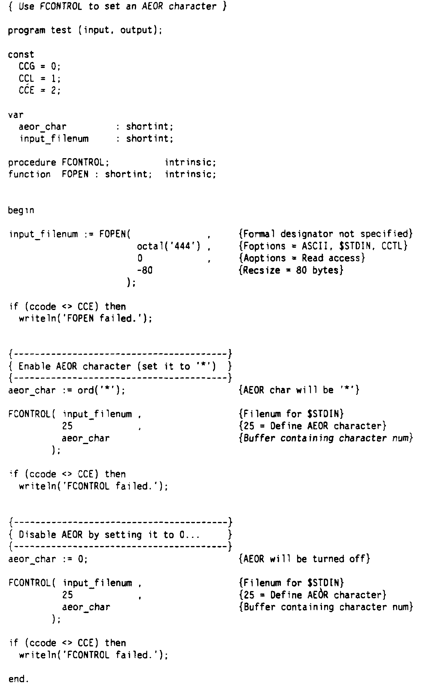
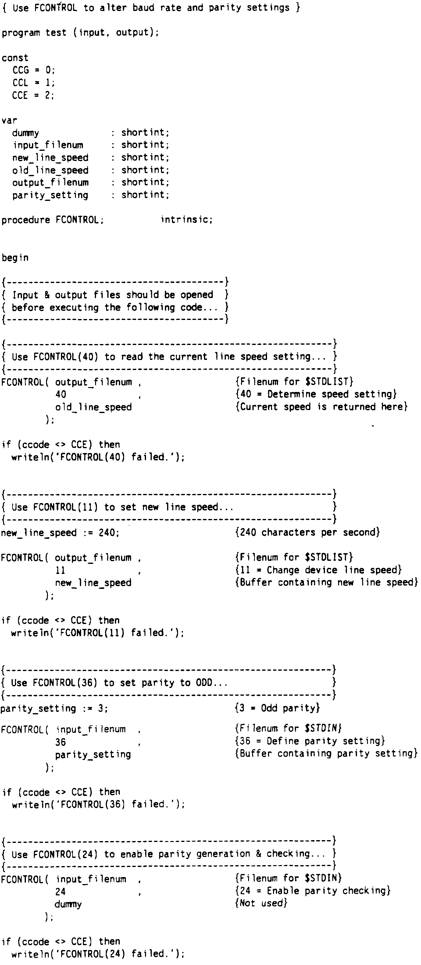
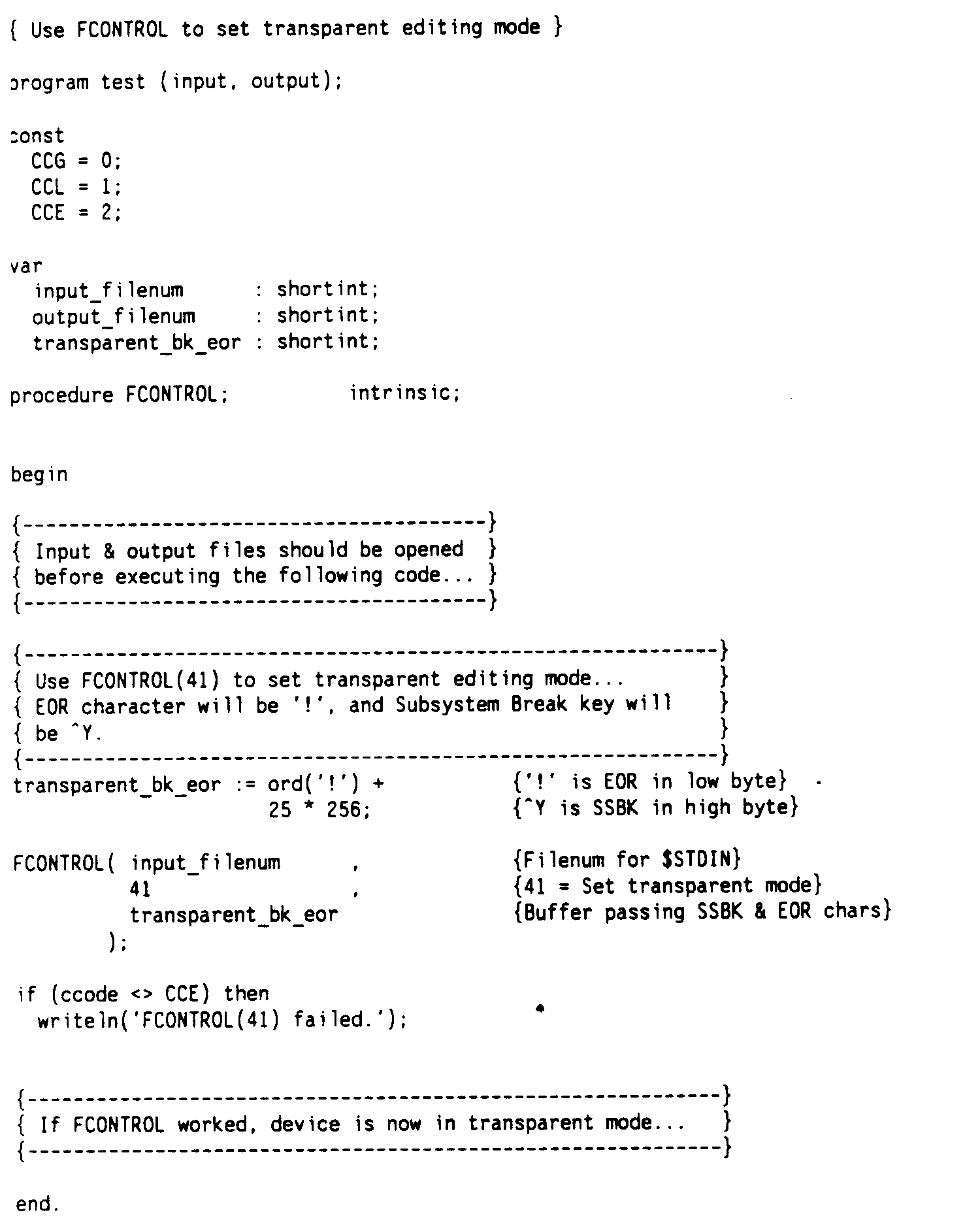
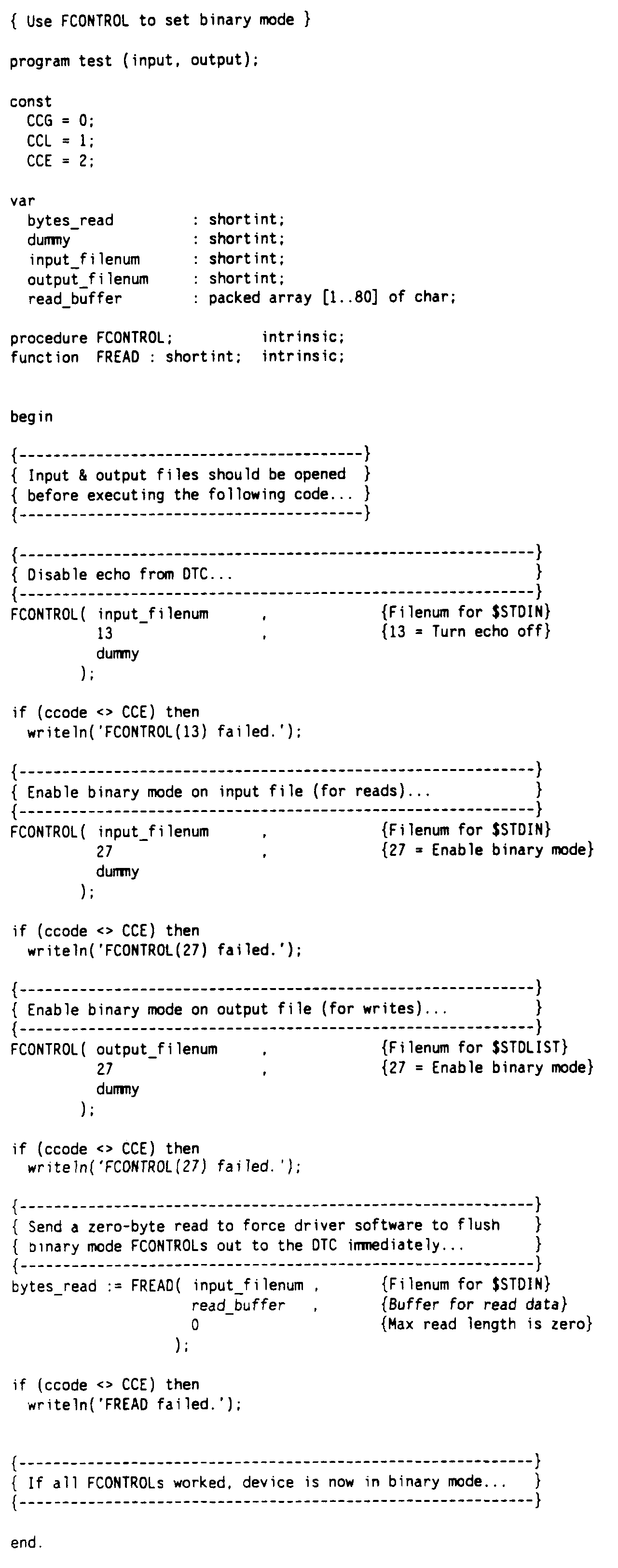
FCONTROL accesses specific devicefiles through their file numbers, as specified in the filenum parameter. The function performed by a particular call to FCONTROL is determined by the controlcode parameter, as is the meaning and use of param. For some controlcode values param has no meaning; in these cases param must be coded as a dummy value to satisfy the requirements of the intrinsic. See Chapter 8 “Intrinsics Reference” for a list of the controlcode values most useful for the control of asynchronous devices and for information on how param is used for each of the controlcode values described. Completion status for each FCONTROL call is indicated through condition codes. See Chapter 2 “Controlling Asynchronous Devices Programmatically” for more information on condition codes. FCONTROL must be called before any data transfer activity in order to have any effect on how that activity occurs. In many cases you will need to use a series of FCONTROL calls to set all of the characteristics desired for a particular transaction. The code fragments that follow illustrate the use of a number of FCONTROL functions. Specifying an AEOR Character Figure 3-6 “Obtaining the Result of the Read Timer” shows how FCONTROL may be used to alter the way in which a read issued against a terminal can be terminated. A controlcode value of 25 is used, which designates that a character, specified through the call, is to be accepted as an Additional End-of-Record (AEOR) character. In this case, an asterisk is designated as the AEOR character. Once an AEOR character is designated, any non-binary mode read issued for that devicefile can be terminated by entry of the AEOR character, as well as in the normal ways, until the device is closed, or until the AEOR character is disabled. You can disable the AEOR character by calling FCONTROL(25) again, using a 0 as the new value for AEOR. A read terminated by means of an AEOR does not end normally. A file system error is returned, indicating that the AEOR character was used. The AEOR character is transmitted with the rest of the read data and is added to the byte count. No carriage return or linefeed is sent to the terminal. See the discussion of FCONTROL(25) in Chapter 8 “Intrinsics Reference” for additional details on this use of the FCONTROL intrinsic. The code fragment presented in Figure 3-7 “Opening a Read Port and a Write Port” shows how a series of FCONTROL calls may be used to perform various device control functions. The end result of such a sequence of FCONTROL calls should be a devicefile whose characteristics are as required for a specific application. The first call in the example, to FCONTROL(40), returns device information to the calling program as the value of the line_speed variable. This call is used to determine the current line speed of the device. Examples of when such a call may be used are to verify a particular setting for an application, or to obtain and store a current value so that a setting can be altered and later reset to its original value. The next call, to FCONTROL(11), changes the line speed of the device to a new value. The value used in the call must be a supported line speed, entered as characters per second (240 characters per second is 2400 bps). The next two FCONTROL calls work together to set a desired parity and enable parity checking. FCONTROL(36) is used in this case to define odd parity as the parity to be used if parity is enabled. Note that setting parity has no effect until parity is enabled. Parity is enabled through the subsequent call to FCONTROL(24). In the FCONTROL(24) call, the third parameter has no meaning. A dummy value must be specified, however, to satisfy the needs of the FCONTROL intrinsic, as well as the needs of the Pascal compiler. The FCONTROL intrinsic is also commonly used to set the data editing mode at a terminal. As explained earlier in this chapter, the data editing mode controls which characters are considered to have special meaning when they are encountered in the data stream. In standard editing mode, all special characters recognized by MPE/iX apply and are acted on when sent from a terminal. However, there are a number of reasons why you might want to suspend the special processing associated with some of these characters. Your application may be using one or more of these characters for a different purpose. Or you may be using an unsupported device which transmits signals that cause problems in standard editing mode. One solution is to enable binary editing mode, which performs no special character processing and allows all characters to pass through as data. However, the use of binary mode severely limits the transmission and terminal control options available to you. Transparent editing mode provides a data editing level between standard and binary editing modes. Because a limited number of special characters retain their meaning in transparent mode, there is much more flexibility in how a data transfer may take place than there is when binary mode is used. For example, you can perform block mode reads while in transparent editing mode, because the block mode control characters (DC1 and DC2) retain their special meanings. (DC2 only has special meaning when received as the first byte of data, however.) Transparent mode also allows you to use parity checking and recognizes and responds to the AEOR character, if one has been designated. If transparent editing mode is enabled for any file, it is also in effect for any other files opened on the same device, regardless of whether or not it was specifically enabled for those files. Also, any FCLOSE issued against the device will return the device to standard editing mode. Subsystem break processing is also available in transparent editing mode. The character that will be recognized as the subsystem break character is passed in the intrinsic call. Any character not otherwise recognized as a special character can be used, including the normal subsystem break character, [CTRL]Y. If a 0 is specified, subsystem break will be disabled. You should note, however, that simply designating a subsystem break character does not enable subsystem break processing. You must still enable subsystem break response and arm the [CTRL]Y trap before the subsystem break function can be invoked. Transparent editing mode will be overridden if you should enable binary editing mode at the same device. However, when you leave binary mode, the device will still be operating in transparent mode. You must explicitly disable transparent editing, either by issuing an FCLOSE against the device, or by calling the intrinsic used to set transparent mode again with both the EOR and subsystem break characters set to null. The code fragment shown in Figure 3-8 “Opening a Read Port and a Write Port” provides an example of enabling transparent editing mode through FCONTROL(41). This FCONTROL uses param to set new values for the EOR character (in the low order byte) and the subsystem break character (in the high order byte). In the example, the bkeor variable is set to 6433, to specify that an exclamation point (!) is the new EOR character and [CTRL]Y is the subsystem break character. Any subsequent read will recognize and treat these characters accordingly and strip them from the input stream. A similar code fragment, setting bkeor to 0, could be used to disable transparent editing mode. See Chapter 4 “Using FDEVICECONTROL” for an example of using FDEVICECONTROL to enable transparent editing mode. In some cases you may need to disable all special character processing and pass everything through as data. Binary editing mode allows you to transfer information in this manner. Binary editing mode treats all characters as data and passes all eight bits of every character through without performing any special operations. Fairly obviously, this restricts the way in which data transfers can take place. You cannot use parity checking in binary mode, since all eight bits of each character are treated as data. Block mode transfers are also impossible, since no special handshake characters are recognized. The only way that a binary read will terminate without returning an error is by reaching the byte count specified in the FREAD, READ, or READX call that initiated the read. Read timeouts will terminate a binary read in error and no data will be transferred. It is a good idea to specify a read timeout value when posting binary reads to avoid problems that can occur if the read does not reach the specified byte count. Binary mode is enabled by calling FCONTROL with a controlcode value of 27 and disabled through FCONTROL with a controlcode value of 26. With either of these FCONTROL calls the third parameter has no meaning and should be invoked with a dummy value of 0. Figure 3-9 “Opening a Read Port and a Write Port” provides an example of enabling binary editing mode in a program. You should note several features of this code fragment, as explained below, to understand how to use binary mode for your own programming needs. Note first that a call to FCONTROL(13) precedes any call to enable binary mode. FCONTROL(13) disables character echo at the terminal. If character echo is not disabled prior to transferring data in binary mode, any ASCII DC3 (XOFF) character in the data (CONTROL S typed at the terminal) would be echoed by the DTC back to the terminal and it would appear to the terminal that the DTC had been XOFFed. This would cause the terminal to hang, since the terminal would suspend transmission to await on XON signal that would never arrive. An alternative to disabling character echo is to turn XON/XOFF flow control off at the terminal. This is a dangerous alternative, however, since disabling flow control may result in write data being lost at the terminal. The next feature of this program you should note is that separate calls to FCONTROL(27) are posted against a read port and a write port on the device. FCONTROL(27) is one of several terminal controls that affect the data transfer characteristics of a specific file, rather than of the device itself. This makes it necessary to explicitly specify binary mode for both the read port and the write port opened on the device. Finally, note that in the example an FREAD call specifying a read of 0 bytes is posted against the device immediately following the FCONTROL calls. Only after the 0 byte read completes successfully does the program notify the user that the port is in binary mode. It is actually the read, not the FCONTROL call, that causes the controlling software to place the device driver in binary mode. (This is only true when you are setting binary mode. Most FCONTROLs take effect at the time the FCONTROL call is issued.) If you are setting binary mode for reads only this is not a consideration, since the first read posted will cause binary mode to be set. If, however, you are setting binary mode for both a read port and a write port, you need to post a read of 0 bytes before assuming that binary mode is set. |
||||||||||||||||||||||||||||||||||||||||||||||||||||||||||||
|
|||||||||