
HP3000 Application Note #6
HP 3000 STACK OPERATION
APP Notes | |
|
Application Note #5 |
Application Note #7 |
HP Part Number: 5958-5824-2620 Published: May 15 1986 Notice
The Response Centers receive many questions regarding the HP 3000's stack architecture and the parameters which control it. This application note, written as a result of these questions, describes the operation of the HP 3000 stack.
Introduction
The HP 3000 is referred to as a "stack machine" because its design is centered around the concept of a stack. A stack is a linear storage area for data, so named because data items can be placed on the "top", "pushing down" the data items already present. When they are no longer useful, data items are removed from the "top", "popping up" those remaining. If you have ever worked with an HP calculator that has an key, then you have worked with a stack.
The benefits of a stack architecture are numerous:
- Storage allocation is dynamic. Local storage is allocated only upon entry to a procedure and is freed upon exit, allowing it to be used by other procedures.
- Temporary storage of intermediate values is automatically provided.
- Code is more compact, because many instructions can assume that their parameters exist at the top of the stack. No extra registers are required for procedure parameters and temporary variables.
- Recursion -- a procedure's ability to call itself -- is possible because each call allocates a new area at the top of the stack.
Stack Layout
Figure 1 shows the layout of the stack area and the way stack registers in the CPU delimit the various parts. Each process has its own (private) stack, but the stack registers, of which there is only one set, point to the currently active process' stack.Registers
The stack area is bounded on the low end by the DL register and at the high end by the Z register. (The system reserves an area before DL and another area after Z; these will be mentioned later. They are inaccessible in user mode.) A major division into two parts is delimited by the DB register, which points to the "base" location of the stack. The area between DL and DB provides a dynamic area for such applications as VPLUS screen information and the Pascal "heap", but it is not accessed by MPE itself. Just as the DB register points to the base location of the stack, so the S register points to the current top-of-stack. The convention of drawing stack diagrams corresponds to the manner in which code is written (or any written language), beginning at the top of the page and proceeding to the bottom. Thus the stack appears inverted, with the last entry (top-of~stack) toward the bottom of the diagram. Addresses increase in a downward direction.
Stack Areas
Having discussed the registers which the system uses to delimit areas of the stack, we can now proceed to a description of those areas. Throughout this section, you may wish to refer back to Figure 1.PCBX
The Process Control Block Extension (PCBX) area contains information necessary for the system to control process activity efficiently, such as register settings and file pointers. Initially, this area is %650 (424 decimal) words long, but it may be expanded by MPE as more files are opened.DL-DB Area
The area from DL to DB is a user-managed global storage area and is not accessed by MPE. Certain subsystems use the 10 words from DB-10 to DB-1, and VPLUS stores its screen buffers and control information here also. BASIC uses the DL area for file buffer allocation and parameter passing. Pascal/3000 also uses this area for its "heap". The size of this area can be changed dynamically by calling the DLSIZE intrinsic.Global Area
This area is used for global variables, declared within the data group of the main program and usable by any procedure within that program. It also contains global arrays and pointers to those arrays. The size of this area is computed by the segmenter at Program preparation time and is stored in the program file. This size, and the content of the global area, are determined by the number of global variables and their initialization as specified by the programmer. This area is delimited by the DB register and the (initial) Q register. At run time, the loader stores the PARM value and INFO string and length in the global area, increasing its size as determined by the length of the INFO string.Woring Stack
From the standpoint of user programs, this is the most active area of the stack -- it is the area where the user's temporary data is stored and manipulated. It is bounded by the addresses contained in Q (initial) and Z. Its size (stacksize) is specified on the :RUN command, the :PREP command, or from a value computed by the segmenter, in that order. The value thus derived is compared with the value configured for STANDARD STACK SIZE, and the larger of these is chosen.Procedure Local area
Within the working stack, this area contains data relating only to the procedure currently executing. The current setting of Q denotes the beginning of this area and S indicates the end, pointing to the last valid item of data in the stack.Available area
Also within the working stack, this area is the space that remains available for new data. It is bounded by the addresses in the S register and the Z register. Z indicates the last main-memory location that can be used by user data in the stack. The size of this area can be changed dynamically with the ZSIZE intrinsic.Stack overflow area
This area is available for stack overflow, a condition that occurs when S must be moved beyond Z and space must be provided for certain end-of-stack information. This buffer area lies between Z and the end of the data segment, and is currently 128 words long.How Procedures Use the Stack
Central to the idea of modular, structured programming is the concept of the procedure. This section describes how the stack is affected by procedure calls and exits.Process initiation
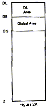
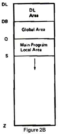
Figure 2A shows how a stack is set up when a process begins execution. Space is first reserved for global data, beginning at the DB address and ending at the Q address, which denotes the beginning of the dynamic working stack. At this time, no data is stored beyond the Q address, so the S register also points to this location. However, as the process continues executing, data is added to the top of the stack and the S register moves away from the location pointed to by Q. See figure 2B.Procedure call
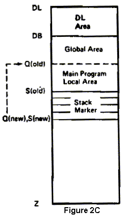
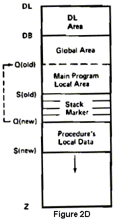
If the process executes a procedure call (PCAL instruction), a new area for data local to that procedure must be defined. Therefore, the hardware places a group of four words called a stack marker on the top of the stack; this information defines the current environment and will be used to reestablish it later, when the called procedure ends. The Q and S registers are then pointed to the top word of this stack marker, and so delimit the beginning of a new, fresh, and unique local storage area for the called procedure (figure 2C). As data is added to the stack during execution of the new procedure, S moves away from (the new) Q, reflecting the latest data added (figure 2D).Exit to caller
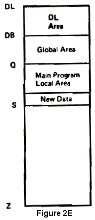
When this procedure returns to its caller, the new local data area is deleted from the stack, and the stack marker is used to restore the previous environment, including the settings for S and Q. This results in a "clean" stack from which storage local to the called procedure is eliminated because it is no longer needed. This space will be reused when the program calls other procedures. See figure 2E.
|
Summary
Whenever a procedure is called, the Q and S registers are manipulated as described above. Q changes with each procedure call and exit, and S may change when an instruction references data. Thus, when a process executes a main program that calls three procedures (main calls A which calls B which calls C), there will be a maximum of four local areas (one for the main and one each for the procedures) on the stack. Each procedure's local area is delimited at its base by a stack marker pointing to the procedure's caller. These markers serve to form a logical chain, from most recent to oldest, that links the current Q register setting back to its initial value.Stack overflow
If a procedure allocates enough local storage, or many nested procedure calls occur, S may move past Z. This condition is known as stack overflow and may or may not cause the program to abort. The operating system will attempt to increase Z, but can only do so as long as the number of words from DL to (the new) Z is less than or equal to MAXDATA (see below). If MAXDATA would be exceeded, MPE aborts the program with a STACK OVERFLOW error message. Since expanding Z may require that the stack be swapped out to disc, MPE tries to expand it more than necessary to rectify the overflow. This reduces the number of times that this overflow processing needs to be performed. MPE never decreases Z; so if a program calls a procedure which allocates a great deal of local storage, and then this procedure exits, there will be a large amount of unused space from S to Z. If the space will not be reused by other procedures, it can be returned to the system by calling ZSIZE to decrease Z; this may result in a small improvement in overall system throughput.Stack parameters
This section describes how the system determines stack size, and what parameters are available to you to modify this value. The total size of the data segment occupied by a stack can be expressed with the following equation:totalsize := pcbxsize + dlsize + globsize + stacksize + storsize
In other words, the size of the stack segment is simply the sum of the sizes of
its components. MPE ensures that totalsize is less than
32,764 words.
Initial pcbxsize is fixed at 4650 (424) words.
dlsize is computed as stated above and the rounded up so
that the sum of it and pcbxsize is an exact multiple of
128 words.
globsize is simply the segmenter-computed size of the
initial DB area. At run time, the three words for the PARM, INFO string length,
and INFO string pointer, plus the INFO string itself, are added to
globsize to arrive at the final value.
stacksize is the number of words from Q (initial) to Z
(initial). Note that this does not include the DB area; instead, it is storage
for the working stack.
storsize is the size of the area reserved for stack overflow
processing. This is a fixed value in MPE and is currently set at 128 words.
DL
This parameter specifies the initial size of the DL area. It can be used on :RUN and :PREP; the value given on :RUN (if any) has precedence. If no DL size is specified anywhere, the system assigns a value of zero. In any case, the system grants sufficient DL area (always rounding up) to assure that the size of the area from the beginning of the PCBX to DB is an exact multiple of 128. This parameter should not be used to attempt to allocate DL space for VPLUS, because VPLUS always allocates DL space in addition to that already in use.STACK
This parameter is used to control the initial size ofstacksize.
It can be used on :RUN or :PREP (RUN has precedence); if not specified there,
the value computed by the segmenter when the program was prepared is used. This
value (from :RUN, :PREP, or the segmenter) is then compared against the system's
STANDARD STACK SIZE as configured in :SYSDUMP and the larger of the two is used.
Typically, the stacksize computed by the segmenter is
sufficient and this parameter need not be specified. If, however, your program
allocates large amounts of local storage when it begins, you may be able to
avoid some of the overhead caused by stack overflow processing (see above) by
using this parameter.
MAXDATA
This parameter, unlike STACK=, does not affect the amount of memory occupied by the stack. Instead, it is used to limit the size of the DL to Z portion of the stack segment and, as a result, controls the amount of Virtual Memory reserved for the stack. MAXDATA must be specified if your program, or anything called by your program, uses the DLSIZE or ZSIZE intrinsics. For example, VPLUS uses DLSIZE to allocate DL space for the Comarea Extension, and programmatic SORT uses ZSIZE to allocate buffer space. MAXDATA may be required if the segmenter's "guesstimate" is not sufficient for a particular program; this is usually uncovered during testing, when the program aborts with a STACK OVERFLOW not attributable to a program bug. In any case, MAXDATA must be specified large enough to accomodate the largest difference between DL and Z. Why not just set MAXDATA to its maximum for every program? For a couple of reasons: 1) This wastes Virtual Memory, which may require a RELOAD (at least a COOLSTART) to reconfigure; and 2) Depending on the circumstances, the File System may not be able to acquire space in the PCBX, which will cause FOPEN to fail with NO MORE ROOM LEFT IN STACK SEGMENT FOR ANOTHER FILE ENTRY (FSERR 74). This last is true because under many conditions, the maximum size of the PCBX is function of MAXDATA: the larger the MAXDATA, the smaller the PCBX.NOCB
This parameter, specified on :RUN (only), tells MPE to mimimize its use of the PCBX for file information. This may permit the DL to Z portion of the stack to be somewhat larger, and it may also avoid the FSERR 74 problem mentioned above. The disadvantage is that the File System may need to use more data segments; this may have a minor negative effect on performance.|
Application Note #5 |
Application Note #7 |