HPlogo HP 9000 Model A-180: User's Manual > Chapter 3 A-Class System Service

A-Class Server I/O Card Removal and Replacement

» 

Technical documentation

Complete book in PDF

 » Table of Contents

Introduction

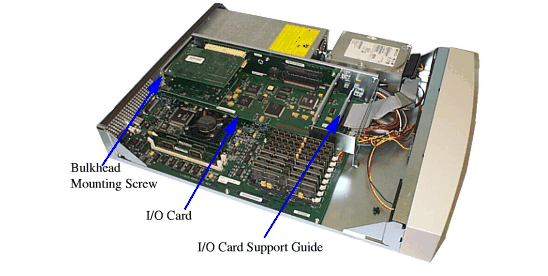
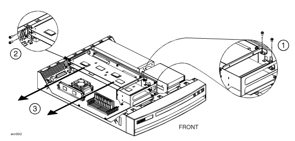
This section provides card load order rules and step-by-step instructions for removing and replacing I/O cards in the A-Class Server. The following subsections apply:

CAUTION: The procedures in this section require opening the system cabinet and exposing the system to electrostatic discharge. Always observe all electrostatic precautions when working with components inside or out of the cabinet. Failure to follow these precautions may result in component damage or loss of system reliability.

Electrostatic Discharge Precautions

  • Use a grounding mat and an anti-static wrist strap.

  • Wear the anti-static wrist strap to ensure that any accumulated electrostatic charge is discharged from your body to ground.

Before You Do Anything...

  1. Perform system backup.

  2. Shut down the operating system.

  3. Power down the system.

  4. Unplug the server.

    NOTE: Cabinet-mounted servers must be removed from the cabinet before proceeding.
  5. Remove the top of the server by unscrewing the knurled captive screws on each side of the rear of the server. Slide the top back, lift it off, and set it aside.

Card Load Order Rules

Card

Rule

Access Port (AP) card

Must go in the bottom slot.

One HSC card and one PCI card

HSC card must go in the bottom slot

All PCI or all HSC cards

Load order doesn't matter.

I/O Card Removal

CAUTION: Always handle I/O cards by their edges. Failure to comply with this precaution may result in damage to the card.
  1. Remove the card support guide screws, then remove the card support guide.

  2. Loosen the mounting screws that secure the bulkhead to the inside of the server chassis. Lower the bulkhead end of the I/O card so that it is free.

  3. Carefully pull the I/O card away from the connector on the backplane and set it on the grounded mat.

NOTE: If two I/O cards are present and the bottom card is to be removed, remove the top card first.

I/O Card Replacement

CAUTION: Keep I/O cards in their protective anti-static bags until you are ready to install them. Always handle I/O cards by their edges after you have removed them from their protective anti-static bags. Be sure that an anti-static wrist strap is still attached to your wrist and grounded to the cabinet main chassis when you handle and install the I/O card. Failure to follow these precautions may cause damage to the I/O card.

I/O card replacement procedures are described as follows:

  1. Carefully insert the I/O card into the backplane connector. The tab on the bulkhead will slide into its slot in the chassis.

  2. Attach the card support guide to the front edge of the I/O card, hook the tab into its slot, and secure the support guide with the mounting screw.

  3. Slide the bulkhead slotted tab up into position between the captive screw and chassis, and tighten the captive screw.

© Hewlett-Packard Development Company, L.P.