HP3000 Application Note #3
Plotter Configuration Guide
APP Notes | |
|
Application Note #1 |
Application Note #4 |

| Plotter Configuration |
| 722X Series |
| 7440A |
| 747X Series |
| 7550A |
| 758X Series |
| 9872 Series |
Plotter Configuration
This guide is intended to be a quick reference for plotter configuration problems. General information on 3000s, terminals and plotters appears first, followed by information on individual plotters, grouped by families.GENERAL INFORMATION
There are three ways to hook up a plotter. You can:- attach it to a separate port on the 3000,
- attach the plotter and a terminal to the same 3000 port (called "eavesdropped"),
- attach the plotter to the back of your terminal via an HP-IB cable (called "slaved").
Separate Port Attachment
This is a very common method of attaching plotters to a 3000, and provides convenient access by a number of different users without having to re-cable equipment. SEPARATE PORT CONFIGURATION. The configuration for the 3000 port is the same for all plotters, and varies only with the revision of MPE. Port speed must match that of the plotter. Configure the port for the linespeed of the plotter to be used. Plotter linespeeds are discussed in the section on individual plotter characteristics. To determine the configuration for a port, use the following guidelines: For plotters connected to ATP ports:
Type 16, Sub-type 0, Term-type 9, Record Width 40, Mode JAID, Driver HIOTERM1
For plotters connected to ADCC ports:
--MPE VIE and later:
Type 16, Sub-type 0, Term-type 9, Rec Width 40, Mode JAID, Driver HIOTERM2 --MPE VIP-delta-I and earlier, including MPE IV:
Type 16, Sub-type 4, Term-type 10, Rec Width 40, Mode JAID, Driver HIOTERM0
For plotters connected to ATC (Series II/III only) ports:
Type 16, Sub-type 0, Term-type 9, Rec Width 40, Mode JAID, Driver HIOTERM2 --MPE VIP-delta-I and earlier, including MPE IV:
Type 16, Sub-type 4, Term-type 10, Rec Width 40, Mode JAID, Driver HIOTERM0
Type 16, Sub-type 4, Term-type 10, Rec Width 40, Mode JAID, Driver IOTERM0
CABLING. Plotters require only pins 2,3 and 7, all straight through. Use
a 13242N, 13242Y, 17255D, or 17355A for a 25-pin port or a 13242X for a 3-pin
ATP port, or equivalent cable. For troubleshooting purposes, HP may require that
the plotter be attached via the appropriate HP supplied cable
LIMITATIONS AND CONSIDERATIONS. With current HP 3000 Business Graphics
software such as DSG and HPDRAW, plotter spooling is NOT supported. The system
spooler interferes with the status checking mechanism of the software, so the
device must run "hot".
Attachment of a plotter via a multiplexer, data switch or other data
communications equipment is NOT supported. In many cases however, plotters will
work when hooked up in this manner. Additionally, there may be software patches
available that permit certain plotters to operate via a data switch or other
equipment; contact the Response Center for additional information. Availability
of a software patch however does not make the configuration a supported one.
Eavesdropping the Plotter with a Terminal
This is a common method of attaching a plotter and a terminal to the same port when the terminal does not have an HP-IB interface. PORT CONFIGURATION. Port configuration for eavesdropped plotters is simple; you don't have any choice. Configure the port for the type of terminal in use with the plotter. LIMITATIONS AND CONSIDERATIONS. Some plotters must be turned on when using the terminal, even if you don't plan to use the plotter. Refer to the section on individual plotters for details. HP-supplied HP 3000 Graphics software does not support plotters attached to an unused RS-232 port on a terminal. The plotter must be between the terminal and the computer or modem. Not only is attaching a plotter to a secondary RS-232 port on a terminal unsupported, it just plain doesn't work. Terminal speed, port speed, and plotter speed must match in order to plot. For example, if terminal speed is 9600 bps and the maximum speed of the plotter is 2400 bps, you must use the MPE :SPEED command to change port speed to 240 before plotting, or log on with the terminal set to 2400 bps. Type "HELP SPEED" at the MPE colon prompt for help with the speed command. Speed should not be a problem if the plotter is turned off. It is possible to use HP Graphics software on one terminal and output to an eavesdrop plotter which is connected to another terminal. However, when you do this, the terminal with the eavesdrop plotter connected cannot be logged on to the HP 3000.Slaved (HP-IB) Attachment
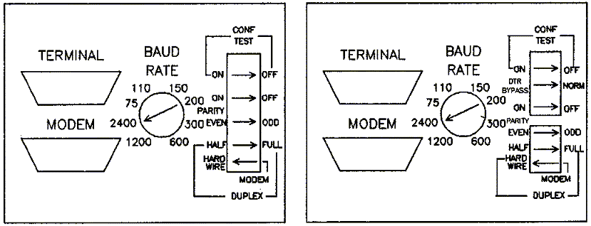
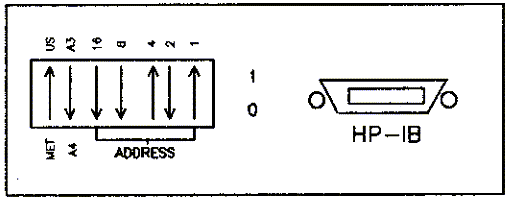
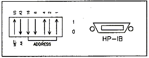
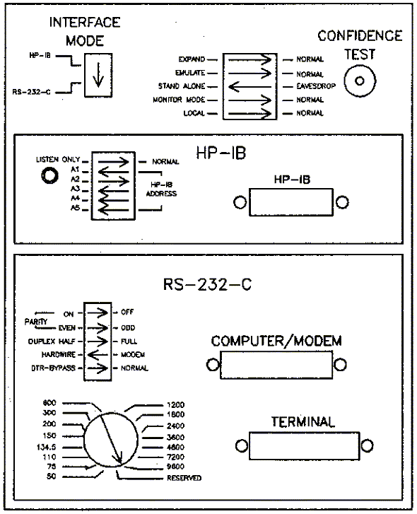
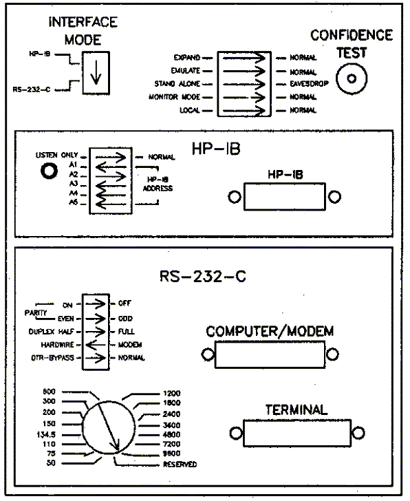
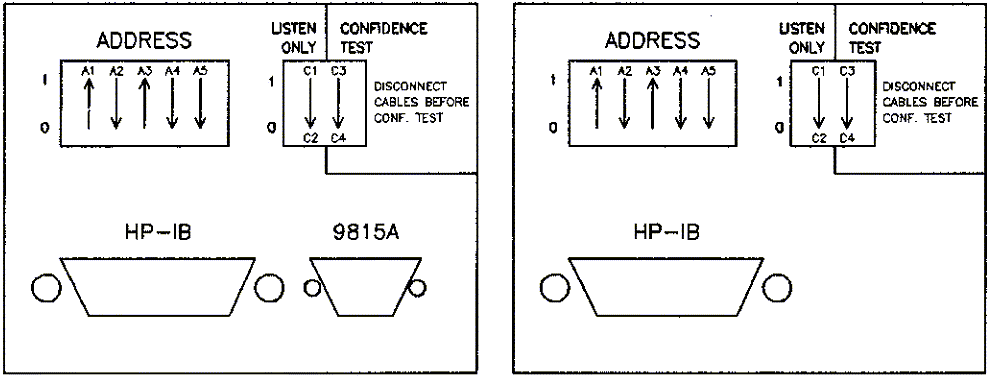
The easiest way to hook up a plotter is to connect it to a terminal via HP-IB. With HP-IB, you don't have to worry about baud rate or cabling, and the plotter never has to be turned on in order for the terminal to work. This requires an HP-IB verison of a plotter and an HP-IB interface on the terminal. Business Graphics on the 3000 default to HP-IB address 5, so that is usually the address at which users operate their plotters. Plotters are shipped from the factory with the address already set to 5. The graphics software will work with different HP-IB addresses, but you'll have to specify this address when you plot. EZCHART only supports plotting on HP-IB address 5. HP-IB addresses on plotters are set like addresses on other HP-IB devices, such as disc drives. Each switch has a binary value of 16, 8, 4, 2, or 1. To calculate the address, add up the total of all the switches in the '1' position, and omit the values of the switches in the '0' position. For instance, to set an address of 7, you would put the "1", "2" and "4" switches in the 'l' position, and all the other HP-IB switches in the '0' position. When changing an HP-IB address, turn off the plotter, reset the switches, then turn the plotter power back on. This will ensure the new address gets set properly. We find that a sharp pencil point works very well for changing switches.722X Series
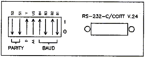
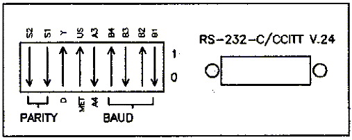
These are flat bed, fixed paper models. They can be connected to a separate port or eavesdropped, but are not found in HP-IB models. This family has a maximum speed of 2400 baud and is no longer in production. The A/B/S models have 4 pens and the CIT versions have 8 pens. The T model is scrollable, the C is not.| 722X A/D/S SWITCH SETTINGS. Set the switches as shown in the diagram below. Adjust the baud rate to terminal and port speeds. | 722X C/T SWITCH SETTINGS. Set the switches as shown in the diagram below. Adjust the baud rate to terminal and port speeds. | |
 | ||
7440A
The 7440A ColorPro Plotter is the low cost 8 pen plotter. It handles A and A4 size paper like the 7470A. This plotter is not currently supported on the HP3000, but may work under certain conditions. The 7440A comes in two options, RS-232 (Option 1) and HPIB (Option 2). The RS-232 version can only be attached to a separate port. This plotter will not work in eavesdrop mode. In addition, the RS-232 version needs a Graphics Enhancement Cartridge (l7440A) to work with HPDRAW and DSG. EZCHART and HPMAP do not currently work with Option 1 of the ColorPro. See the following matrix for a list of what works: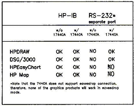
To set the switches of a 7440A RS-232 plotter, turn it off, set the DIP switches according to the tables below, then turn the power back on. The configuration is now set. The baud rate table assumes one stop bit. If you are using two stop bits, see the reference manual for switch settings.
| Rate | B4 | B3 | B2 | Bl |
| 300 | 0 | 1 | 0 | 1 |
| 1200 | 0 | 1 | 1 | 1 |
| 2400 | 1 | 0 | 0 | 0 |
| 4800 | 1 | 0 | 0 | 1 |
| 9600 | 1 | 0 | 1 | 0 |
747X Series
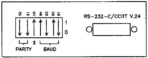
The 747X family of moving paper plotters comes in three flavors, RS-232 (Option 000), HP-IB (Option 002) and HP-IL (Option 003, 7470A only). Option 1 models can operate at 9600 baud and can be separate ported or eavesdropped. Option 2 models can only be slaved. Option 3 7470As are intended for use only with microcomputers with the HP-IL interface installed, and are not supported by 3000 Business Graphics. The 7470A is a two pen plotter, and handles A (8.5 X 11 in.) size paper and A4 (210 X 297 mm) size paper. The 7475A is a six pen model, and handles A and A4, plus B (11 X 17 in.) and A3 (297 X 420 mm) size paper. SETTING 747X OPTION 1 BAUD RATE, PARITY AND OTHER SWITCHES. To set the switches of a 747X RS-232 plotter, turn it off, set the DIP switches according to the tables below, then turn the power back on. The configuration is now set. The baud rate table assumes one stop bit. If you are using two stop bits, see the reference manual for switch settings.| Rate | B4 | B3 | B2 | Bl |
| 300 | 0 | 1 | 0 | 1 |
| 1200 | 0 | 1 | 1 | 1 |
| 2400 | 1 | 0 | 0 | 0 |
| 4800 | 1 | 0 | 0 | 1 |
| 9600 | 1 | 0 | 1 | 0 |
7470A Switches (eavesdrop)
7475A Switches (eavesdrop)
747X Switches (HP-IB)
7550A
The 7550A is a high-speed 8-pen plotter, which can plot on A (8.5 x 11), B (11 x 17), A3 (297 x 420 mm), or A4 (210 x 297 mm) size paper. It has an automatic sheet feeder that can load paper before each plot. The 7550A comes with both RS-232 and HP-IB interfaces, so you can hook it up any of the three ways described below. Configuration of the 7550 is done through the front panel soft keys. There are no DIP switches to set. All configurations changes should begin with powering off the plotter. Some software patches may be available for this plotter. If you are experiencing plotting problems, contact the Response Center for more information. 7550 configuration will be retained when you turn off plotter power. To reset the configuration to factory default, hold down the FAST key while turning on the plotter. SEPARATE PORT CONNECTION OF THE 7550A. Cabling for this type of connection is fairly simple, the only thing to remember is that the connector on the plotter for the computer cable is male instead of female. This means you will need a gender changer cable (part no. 92222F) if you plan to use a standard 13242N male-male cable. To configure the plotter, follow these steps:- Hold down the FAST key and turn on the power. The power switch is on the back, on the lower left corner as you face the front of the plotter. Wait for the pen carousel and plotter arm to stop moving. The plotter is now set to factory defaults.
- Hold down the ENTER key and press NEXT DISPLAY.
- Press the SERIAL softkey.
- Press the DATA FLOW softkey.
- Press the EAVESDROP softkey; it should now display STANDALONE.
- Press ENTER.
Press NEXT DISPLAY. - Press the BAUD softkey.
- Press the 2400 softkey a few times until you reach the baud rate of the port to which you are connecting the plotter.
- Press ENTER.
- Hold down the FAST key and turn on the power. The power switch is on the back, on the lower left corner as you face the front of the plotter. Wait for the pen carousel and plotter arm to stop moving. The plotter is now set to factory defaults.
- Hold down the ENTER key and press NEXT DISPLAY.
- Press the SERIAL softkey.
- Press the DATA FLOW softkey.
- Press ENTER.
Press NEXT DISPLAY. - Press the BAUD softkey.
- Press the 2400 softkey a few times until you reach the baud rate of the port to which you are connecting the plotter.
- Press ENTER.
- Hold down the FAST key and turn on the power. The power switch is on the back, on the lower left corner as you face the front of the plotter. Wait for the pen carousel and plotter arm to stop moving. The plotter is now set to factory defaults.
- Hold down the ENTER key and press NEXT DISPLAY.
- Press the HP-IB softkey.
- Set the HP-IB address. The softkey to the left of the NEXT DISPLAY key increases the address number, the softkey to the right of the LOAD/UNLOAD key decreases the address number.
- Press ENTER.
758X Series
Most 758X drafting plotters come with both RS-232 and HP-IB interfaces, so you have a choice in connecting them. Floor space is usually the limitation here) as these plotters do not fit neatly on a desk. 7580A/7585A. These two models do not come with both RS-232 and HP-IB interfaces. The interface on the plotters depends on which option is ordered; Option 001 is the RS-232 model and Option 002 is the HP-IB model.| Option 001 plotters cannot be eavesdropped. They must be attached to a separate port. Set the switches according to the diagram below. | Option 002 plotters should be set as shown in the diagram below. | |
 | ||
7585B Switches (standalone)
7585B Switches (eavesdrop)

7585B Switches (HP-IB)
9872 Series
These plotters are essentially the 722X models with HP-IB interfaces instead of RS-232 interfaces. Like the 722X models, they are out of production. The S model is scrollable while the A and B models are not. The A model is supported until 11/86 while the B and S models are supported until 2/88. The T model is scrollable, the C model is not.| 9872A/B/S SWITCH SETTINGS. For proper operation, the plotter switches should be set as shown in the diagram below. | 9872C/T SWITCH SETTINGS. For proper operation, the plotter switches should be set as shown in the diagram below. | |
 | ||
|
Application Note #1 |
Application Note #4 |